$45
New Holland Tractor TD3.50 Service Manual - PDF DOWNLOAD
New Holland Tractor TD3.50 Service Manual
FILE DETAILS:
New Holland Tractor TD3.50 Service Manual
Size: 22.2 MB
Format: PDF
Language: English
Number of Pages : 501 pages
Brand: New Holland
Type of document: Service Manual
Model: TD3.50
Part No: 47840677
DESCRIPTION:
New Holland Tractor TD3.50 Service Manual
IMPORTANT NOTICE:
All maintenance and repair operations described in this manual should be carried out exclusively by the NEW HOLLAND authorised workshops. All instructions detailed should be carefully observed and special equipment indicated should be used if necessary. Everyone who carries out service operations described without carefully observing these prescriptions will be directly responsible of deriving damages.
SHIMS:
At each adjustment, select adjusting shims, measure them individually using a micrometer and then sum up recorded values. Do not rely on measuring the entire shimming set, which may be incorrect, or the rated value indicated on each shim.
ROTATING SHAFT SEALS:
To correctly install rotating shaft seals, observe the following instructions:
– Let the seal soak into the same oil as it will seal for at least half an hour before mounting
– Thoroughly clean the shaft and ensure that the shaft working surface is not damaged.
– Place the sealing lip towards the fluid. In case of a hydrodynamic lip, consider the shaft rotation direction and orient grooves in order that they deviate the fluid towards the inner side of the seal.
– coat the sealing lip with a thin layer of lubricant (use oil rather than grease) and fill the gap between the sealing lip and the dust lip on double lip seals with grease;
– Insert the seal into its seat and press it down using a flat punch. Do no tap the seal with a hammer or a drift;
– Take care to insert the seal perpendicularly to its seat while you are pressing it. Once the seal is settled, ensure that it contacts the thrust element if required;
To prevent damaging the sealing lip against the shaft, place a suitable protection during installation.
O RINGS:
Lubricate the O rings before inserting them into their seats. This will prevent the O rings from rolling over and
twine during mounting which will jeopardise sealing.
SEALANTS:
Apply one of the following sealers: RTV SILMATE, RHODORSIL CAF 1, or LOCTITE PLASTIC GASKET over the mating surfaces marked with an X.
Before applying the sealer, prepare the surface as follows:
– thoroughly de-grease the surfaces using one of the following cleaning agents: trichlorethylene, petrol or a
water and soda solution.
TABLE OF CONTENTS:
New Holland Tractor TD3.50 Service Manual
Notes for spare parts2
Notes for equipment 2
Safety Rules 3
Consumables 6
ENGINE SECTION 10
Engine System Chapter 1
Bölüm Tanım Sayfa
10 000 Specifications 2
Tightening Torques14
Special Tools15
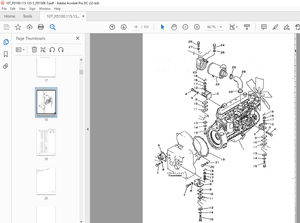
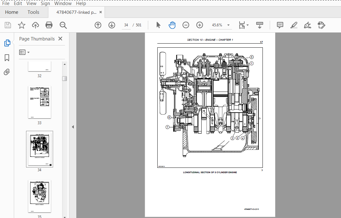
Cross Sectional Views 17
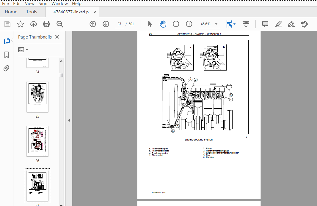
Engine Cooling System 20
Troubleshooting 21
Engine – Remove and Install 25
Engine Removal and Overhaul37
Engine Timing Gear Cover, Timing Gears, and Cam Shaft 44
Cylinder Head 46
Valves 47
Cylinder Block 50
Pistons70
Crankshaft – Main Bearing and Thrust Washer 65
Camshaft 73
Hydraulic Oil Pump83
Description of operation – Engine Lubrication System84
Description of operation – Cooling System86
Clutches Section 18
Section Description Page
18 000 Specifications 1
TIGHTENING TORQUES 2
Special Tools 3
Cross Sectional Views 3
Troubleshooting 4
Remove – Assembly 5-13
Control, Measurement and Repair15-18
General Maintenance – Overhaul 18-19
Clutch Adjustments 20-22
TRANSMISSION SECTION 21
Mechanical Transmission Chapter 1
Section Description Page
21 000 Specifications 2
Tightening Torques
Liquid Sealants 4
Special Tools 5
Cross Sectional Views 6
Troubleshooting 8
Description and Operation8
Reverser Chapter 2
Section Description Page
General Recommendations For Overhauling Operations 2
Transmission Assembly, Removal – Installation 3
Transmission – Mechanical – Disassemble 8×8 Shuttle Transmission 18
Gear and Synchroniser – Remove Transmission Synchroniser Kit and Cluster
Gear Assembly 24
Gear and Synchroniser – Inspect Transmission Synchroniser Kit and Cluster Gear Assembly28
Gear and Synchroniser – Install Transmission Synchroniser Kit and Cluster Gear Assembly 29
DRIVE LINES SECTION 23
Drive Lines Chapter 1
Section Description Page
23 000 Specifications 1
Torque Settings and Tools2
Cross-Sectional Views 3
Transmission shafts and guard (Disassembly – Assembly) 4
Drive gear housing (Removal – Installation) 5
Drive gear housing removed (Disassembly – Assembly)6
FRONT AXLE MECHANICAL TRANSMISSION SECTION 25
Front Axle Mechanical Transmission Chapter 1
Section Description Page
25 000 Specifications 2
TIGHTENING TORQUES 3
Tools 6
Cross Sectional Views 7
Description and Operation 9
25 100 30 Complete front axle Remove – Install 10
25 100 38 Front axle Remove – Install 15
25 108 46-47 Steering knuckle bearing pins Replace 22
Stub axle adjustment 23
Wheel hub bearing adjustment25
Bevel drive adjustment 26
25 102 24 Front Axle Differential Overhaul 32
25 100 27 Front axle differential with LIM-SLIP Overhaul 33
44 511 80 Leading drive wheels toe-in check 35
REAR AXLE AND TRANSMISSION SECTION 27
Rear Axle And Transmission Chapter 1
Section Description Page
21 000 Specifications 2
Tightening Torques 3
Liquid Sealants 6
Special Tools 7
Cross Sectional Views 7
Troubleshooting 10
Description and Operation10
Low Gear Drive Line Schema 13
Reverse Gear Drive Shaft13
High Gear Drive Shaft 14
Transmission Assembly, Removal – Installation 16
Internal Components, Disassembly – Assembly 33
Diferential Chapter 2
Section Description Page
27 000 Differential Assembly 2
Differential pinion and side gear backlash 4
Repair and Inspection 5
Adjustment of bevel wheel bearings and crown pinion backlash adjustment 6
Final drive housing 8
POWER TAKE-OFF SECTION 31
Mechanical Power Take – Off Chapter 1
Section Description Page
31 000 Specifications 1
Tightening Torques 2
Liquid Sealants 3
Cross Sectional Views 4
Description and Operation 5
RemovalInstallation – Overhaul 7
BRAKING SYSTEM SECTION 33
Braking System Chapter 1
Section Description Page
33 000 Specifications 2
Tightening Torques 3
Special Tools 4
Liquid Sealants 4
Cross Sectional Views 5
Troubleshooting 6
Description and Operation7
Brake Control, Removal – Installation 8
Brake Assembly, Removal – Installation 10
Brake Pedal Free Play Setting 13
HYDRAULIC SYSTEM SECTION 35
Hydraulic System
Chapter 1
35 000 Introduction and Circuit Identification 1
Open Centre High Pressure Hydraulic Circuit 3
Hydraulic Circuit Diagram4
Sectional view5
Hydraulic Pump
Chapter 1
Specifications 1
Tightening Torques 2
Special Tools 2
Description and Operation3
Remove and Install 4
Disassembly – Assembly 5
Hydraulic Pump
Chapter 2
35 000 Specifications 2
Tightening Torques 3
Liquid Sealants 4
Special Tools 4
Cross Sectional Views 5
Troubleshooting 7
Description and Operation8
Operation of Distributor 12
Internal Three-Point Hitch15
Operation of Internal Lift-O-Matic Levers 21
Remove and Install 23
Disassembly – Assembly 25
Adjustment and Settings 38
STEERING SECTION 41
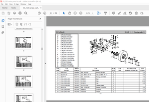
Steering Chapter 1
Section Description Page
Section Description Page
41 000 Specifications 1
Tightening Torques 3
Special Tools 3
Troubleshooting 3
Description and Operation8
Removal Installation – Overhaul12
ELECTRICAL SYSTEM SECTION 55
Instruments Section 1
Section Description Page
Semi-digital instruments Introduction 1
Transmitters, sensors and switches 3
Components Chapter 2
Section Description Page
55 500 Introduction 1
Description of the Component 2
Starting System Chapter 3
Section Description Page
55 000 Technical Information1
TIGHTENING TORQUES 1
Description and Operation 2
Starter System Circuit 3
Operation Description 5
Removal and re-installation of starter motor 7
Electrical Test 8
Bench tests 10
Charging System Chapter 4
Section Description Page
55 000 Technical Information1
TIGHTENING TORQUES 1
Description and Operation 2
Alternator – Removal and Reassembly4
Alternator component testing and inspection 10
Battery Chapter 5
Section Description Page
55 000 Technical Information1
Description and Operation 1
Removal and Re-installation 2
Battery Checking and Maintenance 3
Battery Charging 4
Battery Problems – Frequent Causes 7
IMAGES PREVIEW OF THE MANUAL:

PLEASE NOTE:
More products