$20
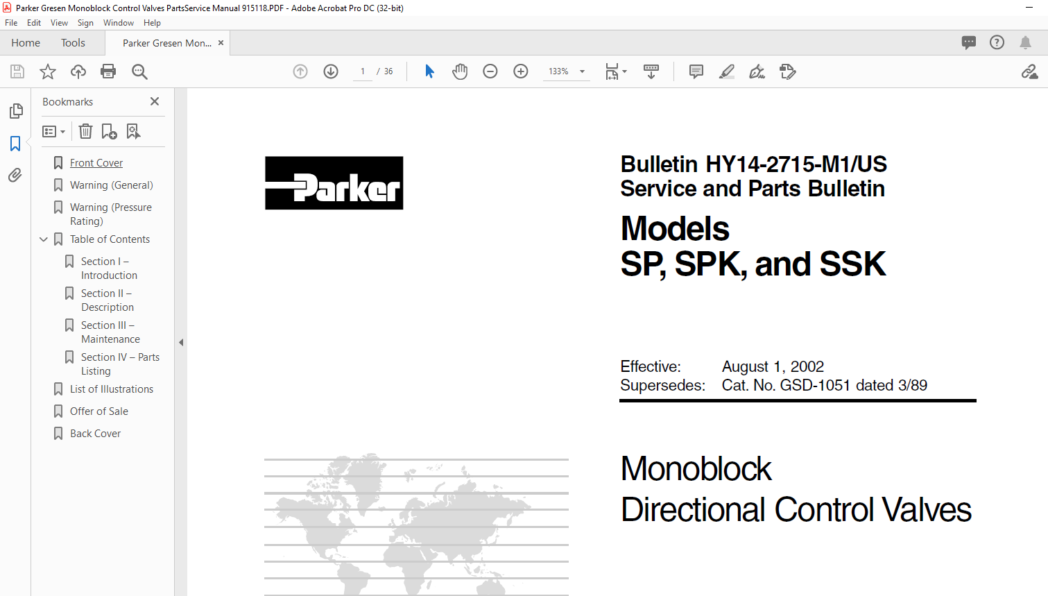
Parker SP SPK & SSK Gresen Monoblock Control Valves PartsService Manual 915118 – PDF DOWNLOAD
Parker SP SPK & SSK Gresen Monoblock Control Valves PartsService Manual 915118 – PDF DOWNLOAD
FILE DETAILS:
Parker SP SPK & SSK Gresen Monoblock Control Valves PartsService Manual 915118 – PDF DOWNLOAD
Language : English
Pages : 36
Downloadable : Yes
File Type : PDF
Size: 3.76 MB
IMAGES PREVIEW OF THE MANUAL:

DESCRIPTION:
Parker SP SPK & SSK Gresen Monoblock Control Valves PartsService Manual 915118 – PDF DOWNLOAD
INTRODUCTION:
The Models SP, SPK and SSK Monoblock Directional Control Valves may be purchased with many combinations of spools, spool positioners and relief options to meet the desired job specifications or applications. The following paragraphs describe the 3 valve models and their respective options with references to the parts illustrations in Section IV in this manual.
- In some cases, identification of a specific part or component may only be made by comparision with these parts illustrations. MODEL SP DIRECTIONAL CONTROL VALVE (Refer to Figure 4-1) The Model SP 1-, 2-, or 3-spool Valve can be identified by the number 2701, 2702 or 2703 stamped on the housing.
- This is a parallel circuit valve. The open center passage is closed off when the spool is fully shifted and hydraulic oil will flow directly to the power core passage, making oil available to all work ports. If two or more spools are fully shifted at the same time, the oil will follow the path of least resistance, and the hydraulic cylinder or the hydraulic motor with the lightest load will begin to function first.
- The hydraulic oil can be divided so that it will flow to two or more functions by metering the spools. The parallel circuit is the most commonly used circuit in mobile equipment because more than one function can be operated at the same time at random in the valve bank assembly.
TABLE OF CONTENTS:
Parker SP SPK & SSK Gresen Monoblock Control Valves PartsService Manual 915118 – PDF DOWNLOAD
Contents——————-Page
No
Section I Introduction 2
Section 11 Description 3
Section 111 Maintenance 5
Section IV Parts L isting 8
Factory Warranty 34
List of Illustrations—————
Figure 4-1 Models SP 1-, 2- and 3-Spool Directional Control Valves 8
Figure 4-2 Models SPK 1-, 2- and 3-Spool Directional Control Va lves 10
Figure 4-3 Model SSK 2-Spool Directional Control Valve 12
Figure 4-4 Model J Standard Relief 14
Figure 4-5 Model J-HP High Pressure Relief 15
Figure 4-6 Model J-NJ Non-Adjustable Relief 16
Figure 4-7 Model J-NJ-HP Non-Adjustable High Pressure Relief 17
Figure 4-8 Models WK and WS Non-Adjustable;
WKA and WSA Adjustable Differential Poppet Type Relief 18
Figure 4-9 Plug “NR” (No Relief) 20
Figure 4-10 Load Check 20
Figure 4-11 Spring Return to Neutral Positioner 21
Figure 4-12 Manua I Positioner 22
Figure 4-13 4-Position Float Posit ioner 23
Figure 4-14 2-Position or 3-Position “D” Detent Positioner (After early 1974) 24
Figure 4-15 1-Posit ion “R” Detent w ith Spring Return to Neutral 25
Figure 4-16 Rotary “W” Detent Positioner 26
Figure 4-17 Spring Extended “A” Spool Positioner 27
Figure 4-18 Spool Travel “L” Limiter 28
Figure 4-19 Closed Center Plug Kit · 29
Figure 4-20 Power Beyond Kit 30
Figure 4-21 Conversion Plug Kit 31
Figure 4-22 Handle Assembly, Short : 32
Figure 4-23 Handle Assembly, Standard 32
Figure 4-24 Handle Assembly, Offset to Right 33
Figure 4-25 Handle Assembly, Offset to Left 33


