$35
Peterbilt Truck 270 Operator's Manual - PDF DOWNLOAD
Peterbilt Truck 270 Operator's Manual - PDF DOWNLOAD
FILE DETAILS:
Peterbilt Truck 270 Operator's Manual - PDF DOWNLOAD
Language :English
Pages :127
Downloadable : Yes
File Type : PDF
IMAGES PREVIEW OF THE MANUAL:

DESCRIPTION:
Peterbilt Truck 270 Operator's Manual - PDF DOWNLOAD
FOREWORD
How to use this handbook
- This handbook contains information for you, the driver, to enable you to operate the vehicle as efficiently and safely as possible and generally to make your driving easier and more satisfying. Besides subjects such as operating instructions, attention also focuses on maintenance and minor repairs which you may be able to carry out yourself.
- The vehicles covered by this handbook consist of various types and models. Individual vehicles are constructed in accordance with all Federal Motor Vehicle Safety Standards and in accordance with the expected operating conditions. Certain descriptions or illustrations in this handbook may therefore not correspond entirely to the situation on your own vehicle. However, this has no influence on its operation or maintenance.
TABLE OF CONTENTS:
Peterbilt Truck 270 Operator's Manual - PDF DOWNLOAD
PB1340Apdf 0
Foreword 3
How to use this handbook 3
Safety Signals 3
WARNING 5
CAUTION 5
NOTE 5
Contents 7
General 9
Safety Precautions 9
General 9
Engine 9
Cooling System 9
Components 10
Electrical 10
Oils and Lubricants 11
Maintenance Activities 11
Chassis Frame 11
Welding 11
All Electronic Engines 11
All Anti–Lock Braking Systems (ABS) 12
Vehicle Load 12
Fire Extinguisher 12
First Aid Kit 12
Winter Driving Conditions 12
Items of Special Importance 13
Break-in 13
Cooling System 14
Air Leakage 14
System Voltage 14
Batteries 14
Battery Charging 15
Jump Starting Vehicles 15
WARNING! Batteries can injure you severely They contain acid, produce poisonous and explosive ga 15
WARNING! Do not allow battery fluid to contact eyes, skin, fabrics, or painted surfaces Always w 16
To Jump Start Your Vehicle 16
CAUTION: Applying a higher voltage booster battery will cause expensive damage to sensitive elect 16
WARNING! To avoid serious personal injury and damage to the vehicle, heed all warnings and instru 16
Preparing the vehicles: 17
1 Position the two vehicles together, but do not let them touch 17
2 Turn OFF all lights, heater, radio, and any other accessories 17
3 Set the parking brakes 17
4 Ensure that the transmission is in neutral position or, if auto shift, that it is in park posi 17
5 Turn engine OFF (booster vehicle) 17
6 Disconnect ground cable on booster battery 17
Connect the batteries: 17
1 Attach one end of a jumper cable to the positive terminal of the discharged (dead) battery Th 17
2 Start the engine: 17
Remove jumper cables: 18
Protecting the Environment 18
Cleaning the Vehicle 19
Cleaning the Cab 20
Waxing the Cab 20
Cleaning the Cab Interior 20
Getting to Know Your Vehicle 21
Cab 21
Entry and Exit 21
To help avoid personal injury due to a slip or fall: 21
Doors 22
Tilting the Cab 22
Tilting 23
Lowering 23
Door Mirrors 24
Mirror head attachment 24
Mirror arm fold positions 24
Windshield Wiper Blades 25
Seats 25
WARNING! Do not adjust the driver's seat while the vehicle is moving The seat could move suddenl 25
Driver's Seat (adjustable) 26
Fore/aft adjustment 26
Seat cushion height adjustment- front 26
Seat cushion height adjustment-rear 26
Backrest adjustment 26
Passenger's Seat (2-man) 26
Passenger's Seat (single-adjustable) 26
Seat Belts 26
WARNING! Always wear your seat belt low over your pelvic bones 27
WARNING! Do not twist the belt in the process of putting it on A twisted belt will not work as w 27
Seat belt upper anchorage adjustment 28
Seat belt care 28
Storage Tray 29
Glove Box 29
Sun Visors 30
Roof Vent (option) 31
Courtesy Lights 31
Interior Light Unit 32
Courtesy interior light 32
Position A: 32
Position B: 32
Position C: 32
Reading light 32
Ashtray 32
Cigarette Lighter 32
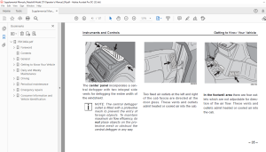
Instruments and Controls 33
General 33
Warning Lights 33
Red 33
Amber 33
Green Or Blue 33
Instrument Panel 34
1 Tachometer 35
2 PTO warning light 35
3 High beam warning light 35
4 Hazard switch warning light 35
5 Turn signal warning light - vehicle 35
6 Cruise control warning light 35
7 Cab-lock warning light 35
8 Oil pressure warning light 35
9 Low air pressure warning light 35
10 Battery charge warning light 35
11 Parking brake warning light 35
12 Not used 35
13 Differential lock warning light 35
14 ABS warning light 35
15 Maintenance - Water in Fuel 35
16 Check engine warning light 35
17 Stop engine warning light 35
18 Coolant temperature warning light 35
19 Wait to Start engine warning light 35
20 Transmission oil temperature warning light 35
21 Check transmission warning light 35
22 Fuel gauge 35
23 Coolant temperature gauge 35
24 A/C On-Off switch 35
25 Heating and ventilation controls 35
26 Ventilation fan indicator light 35
27 Air pressure gauge (secondary) 35
28 Fuse box - right 35
29 Air pressure gauge (primary) 35
30 Speedometer/odometer 35
31 Fuse box - left 35
32 Vehicle lighting switch 35
33 Cruise control Set/Resume switch 35
34 Cruise control On-Off switch 35
35 Hazard warning light switch 35
Switches, Gauges, and Warning Lights on the Instrument Panel 36
1 Tachometer 36
2 PTO Warning Light 36
3 High Beam Warning Light 36
4 Hazard Switch Warning Light 36
5 Turn Signal Warning Light - Vehicle 36
6 Cruise Control Warning Light 36
7 Cab-lock Warning Light 36
8 Oil Pressure Warning Light 36
WARNING! The air pressure warning light and the audible alarm indicate a dangerous situation: the 37
Air Loss Emergency Procedure 37
1 Slow down carefully 37
2 Move a safe distance off the road and stop 37
3 Place the transmission in park and set the parking brake (See pages 58 and 66 for transmissio 37
4 Turn OFF the engine 37
5 Turn ON the emergency flasher and use other warning devices to alert other motorists 37
9 Low Air Pressure Warning Light 37
10 Battery Charge Warning Light 37
11 Parking Brake Warning Light 37
13 Differential Lock Warning Light 37
14 ABS Warning Light 38
15 Maintenance - Water in Fuel 38
16 Check Engine Light 38
17 Stop Engine Light 38
18 Coolant Temperature Warning Light 38
19 Wait to Start Light 39
20 Transmission Oil Temperature Warning Light 39
21 Check Transmission Warning Light 39
22 Fuel Gauge 39
23 Coolant Temperature Gauge 40
24 A/C On/Off Switch 40
25 Heater And Air Conditioner Controls 40
WARNING! Excessive heat may cause the pressurized components of the air conditioning system to ex 41
Slide control 3 42
Air vents and defoggers 42
Heating 44
Defogging 45
Cooling 45
For Efficient Cooling: 45
1 Ensure all heater/air conditioner controls are off 45
2 Start the engine Allow time for warm–up 45
3 Set the air conditioner for maximum cooling 45
4 Close all windows 45
5 Idle the engine between 1,000 and 1,500 rpm and turn the fan switch to High 45
6 After the cab temperature cools to a comfortable level, adjust the fan speed and other control 45
7 For efficient air flow in fresh air mode, regularly clean the HVAC filter located on the botto 45
27 Air Pressure Gauge “Secondary” 46
28 Fuse Box - Right 46
29 Air Pressure Gauge “Primary” 46
31 Fuse Box - Left 47
32 Vehicle Lighting Switch 47
OPERATING LEVER, PARKING BRAKE 49
CENTER ROOF CONSOLE 50
Interior Light 51
Mirror Heating Switch 51
Instrument Panel Lighting Switch 51
Controls Around The Steering Column 52
Adjustable Steering Column 53
Multi-function Switch, Left 53
Headlight flash, low beam, high beam 53
Position H: 53
Position I: 53
Position J: 53
Turn Signals 53
Position L: 53
Position H: 53
Position R: 53
Horn 53
Multi-function Switch, Right 54
Windshield wipers 54
Position A: 54
Position B: 54
Position C: 54
Position D: 54
Windshield washers 54
Chassis 54
Towing Pin 54
Daily and Weekly Maintenance 55
Driver's Check List 55
Approaching Your Vehicle 55
Daily Checks 55
Engine Compartment 55
1 Engine Fluid Levels—add more if necessary 55
2 Engine Belt—check tension and condition of belts per engine manufacturer’s Operation and Maint 56
Retensioning New Belts 56
3 Fuel Filter/Water Separator Draining—check and drain Depending on the fuel storage facility, 56
4 Windshield washer reservoir fluid level—fill if necessary 56
Chassis and Cab 56
1 Lights—do headlights, turn signals, emergency flashers, and exterior lamps function and are th 56
2 Windows and Mirrors—are they clean and adjusted properly? 56
3 Tires and Wheels—are they inflated properly? Are all wheel cap nuts in place and torqued prope 57
4 Suspension—check for loose or missing fasteners Check damage to springs or other suspension p 57
5 Brake Components—check lines, linkages, chambers, parking and service brake operation 57
6 Air System—are there leaks? 57
7 Steps and Handholds—check for worn surfaces and loose or missing fasteners 57
8 Fluid Tanks—check underneath the vehicle for signs of fluid leaks If any are found, correct b 57
9 Fuel Tank Caps—are they secure? 57
Cab Interior 57
1 Seat—adjust the seat for easy reach of controls 57
2 Seat Belts—fasten and adjust safety restraint belts 57
3 Steering Column—adjust for easy reach 57
4 Mirrors—check and readjust mirrors if necessary 57
5 Lights—turn ignition key to the ON position and check for warning lights and buzzer Check ope 57
6 Instruments—check all instruments 57
7 Windshield—check operation of windshield wipers and washers 57
8 Horn—check operation of horn 57
9 Storage Compartment—all loose items stowed securely Is the fire extinguisher fully charged? I 58
10 Fuel—check fuel Is there enough fuel? 58
Daily Maintenance 58
Front Access Panel 58
Engine Oil Level 58
1 The vehicle must be parked on flat and level ground 58
2 Pull the dipstick (1) out of the dipstick tube and wipe it clean with a lint-free cloth 58
3 Place the dipstick completely back in the dipstick tube 58
4 Withdraw the dipstick again and check the oil level; the oil level should always be between th 58
5 If necessary, add oil through the filler opening (2) Always use oil of the same brand and gra 59
Coolant Level 59
1 Remove the filler cap (1) and check that the engine coolant is level with the lower lip of the 60
Wheels And Tires 60
Lighting And Instruments 60
Driver's Seat And Mirrors 60
Weekly maintenance 61
Power Steering Fluid Level 61
1 Thoroughly clean the area around the dipstick 61
2 Check the fluid level in the reservoir with the dipstick 61
3 With the engine running, the fluid level should be up to the upper mark (MAX) on the dipstick 61
Air Filter Restriction Indicator 61
Brake System Air Dryer (optional equipment) 62
1 Chock the road wheels and fully charge the vehicle air system 62
2 Pull each air reservoir drain valve ring and check that the expelled air is free of any conden 62
Clutch Fluid Level 63
1 Open the cab front panel to gain access to the clutch reservoir 63
2 Check that the hydraulic fluid level registers on or above the level mark (5), molded on the c 63
Windshield Washer Fluid Level 64
1 Open the cab front panel to access the reservoir filler tube 64
2 Remove the filler cap and refill the reservoir with a suitable windshield cleaning solution 64
Tires 64
Driving 65
General 65
Ignition Switch 65
Starting Procedure 66
1 Ensure that the parking brake is applied and the shift lever is in the neutral position 66
2 Turn ignition key to position `C' and check that the oil pressure and parking brake warning li 66
3 If the engine WAIT light is on, wait until it goes out 66
4 With the accelerator pedal released, turn the ignition key to position D; release the key imme 66
Operating the Transmission 66
Introduction 66
Operating Manual Transmissions 67
Transmission Warm–Up 67
1 Put the transmission in Neutral 67
2 Release the clutch pedal and let the transmission operate in Neutral for three to five minutes 67
Putting the Vehicle in Motion 67
1 Fully depress the clutch pedal and shift the transmission into first gear 68
2 Lift the sleeve on the parking brake handle and push the handle fully forward to release the b 68
3 Release the clutch pedal, then gradually accelerate 68
4 Do not allow your vehicle to roll (even a little) in the opposite direction during clutch enga 68
Shifting Gears in a New Vehicle 68
More Transmission Tips 69
“Riding” the Clutch 69
Release Bearing Wear 69
Clutch Adjustment 69
Tips for Manual Transmission Operation 69
Operating Automatic Transmissions 70
The MD Automatic Transmission 70
Operating Automated Manual Transmissions 71
Cruise Control 72
Engaging the Cruise Control 72
1 Move the ON/OFF switch to the ON position 72
2 Accelerate the vehicle to the desired cruise speed 72
3 Toggle the SET/RESUME switch to the SET position to set the cruise speed 72
Disengaging the Cruise Control 72
Reengaging the Cruise Control 73
1 Move the ON/OFF switch to the ON position 73
2 Toggle the SET/RESUME switch to the RESUME position 73
Steering 73
Brakes 73
Anti-Lock Braking System (ABS) 73
WARNING! Do not rely on an anti-lock brake system that is functioning improperly You could lose 73
Service brakes 74
Parking brake / emergency brake 74
Engine Exhaust Brake (option) 75
WARNING! The service brakes must be used in an emergency The engine exhaust brake alone might no 75
Exhaust Brake Operation 76
Stopping 77
Parking 77
Turning off the engine 77
Diesel Fuel 78
Cold Weather Recommendations 78
Periodical maintenance 79
General 79
Maintenance and Lubrication Intervals 80
Table 1 Recommended Maintenance Intervals 80
Maintenance Schedule 83
Table 2 Maintenance Schedule 83
Lubrication Specifications 91
CAUTION: Do not mix different types of lubricants Mixing lubricants (oil and grease) of differen 91
Lubrication Types 92
BB: 92
CB: 92
CC/CD: 92
CD: 92
CE: 92
CL: 92
EP: 92
GL: 92
HD: 92
HT: 92
SD: 92
PS: 92
Table 3 Lubricant Applications 92
Oil Reservoirs 93
Lubrication Chart 93
Table 4 Recommended Lubrication Types 94
Maintenance in Special and Exceptional Operating Conditions 96
First Service 96
Cab Maintenance 96
Preventive Maintenance Before the Winter Season 96
Checking the Anti-freeze Content 96
1 Remove the filler cap from the surge tank 97
2 Using 2-way test strips, perform freeze point and nitrite level tests per coolant supplier’s r 97
3 The cooling system should be filled with ready-mixed clean water/anti- freeze solution which c 97
NOTES 98
Emergency repairs 99
Vehicle Tool Kit 99
Replacing The Drive Belt 99
Drive belt tension 99
Replacing The Compressor Belt 99
1 Disconnect the batteries, negative terminal first, then positive terminal 99
2 Fully tilt the cab 99
3 Loosen the adjusting screw retainer bolt (1), but do not remove 99
4 Loosen the jam nut (3) 99
5 Loosen the tensioning bolt (4) 99
6 Pivot the compressor to slacken the belt 99
7 Remove the compressor belt (5) 99
8 Clean the pulleys and ensure that they are free of any contaminants (oil/fuel/dirt)100
9 Install a new belt100
10 Pivot the compressor to tighten the belt and hold the tension by setting the adjustment screw100
11 Lower the cab and re-connect the batteries, positive terminal first100
Replacing The Fuel Filter100
Adjusting The Brakes100
Spring Brakes — Manual Release100
WARNING! Do not disassemble a spring brake chamber These chambers contain a powerful spring that101
1 Block the wheels with chocks101
2 Remove the cap from the spring chamber101
3 Remove the release stud assembly from the side pocket, and remove the release nut and washer f101
4 Slide out the release stud102
5 Insert the release stud through the opening in the spring chamber where the cap was removed I102
6 Assemble the release stud washer and nut on the release stud102
7 With a wrench, turn the release stud assembly nut until the compression spring is 90–95 percen102
Jacking The Vehicle102
Wheels103
Changing wheels103
1 Chock the road wheels and position the jack under the appropriate axle, as close as possible t103
2 Clean the wheel nuts or, if applicable, remove the protective cover from each wheel nut103
3 Loosen, but do not remove the wheel nuts103
4 Jack the axle until the road wheel(s) are clear of the ground Remove the road wheel nuts and 103
5 Before installing the road wheel, carefully clean the mating edge of the wheel hub and the inn103
6 Install the wheel and gradually tighten the wheel nuts in a crisscross sequence to 450 to 500 104
Towing Pin105
Towing105
Replacing Bulbs106
Headlights106
1 Remove four Torx head screws from the side marker light assemblies There are two on each side106
2 From behind the side marker lights, cut tie straps106
3 Pull assembly out and carefully remove the two inline connections on each side by carefully pu106
4 Remove four bolts from the front of the headlight grille, two on each side106
5 Remove two nuts from the back of the headlight grille106
6 Remove two center screws from the step plate in the center of the headlight grille106
7 Remove the headlight grille106
8 Remove four screws holding the headlight bezel in place and remove the headlight106
9 Replace the headlight and bezel106
10 Reverse the disassembly procedure and assemble all removed parts Be sure to replace tie straps106
Front Marker Lights106
Side Marker Lights107
1 Remove two torx head screws (1)107
2 From behind side marker light assembly, clip tie wraps107
3 Pull assembly out and carefully remove the two inline connections (2) by pulling them apart107
4 Remove the sheet metal nut and carefully pry marker light off adhesive-backed foam107
5 If necessary, replace adhesive- backed foam pad107
6 Replace marker light107
7 Replace tie wraps107
Side Lights107
1 Find the tab on the yellow lens Using a narrow blunt tool, such as a flat screwdriver, pry of107
2 Change bulb107
3 Replace lens107
Rear Lights107
1 Locate the two tabs at the bottom of the housing Pop open (down)107
2 Lift outer cover and remove sealed lamp and install new one107
3 Lower cover and snap tabs back in place107
Turn signal, front107
1 Remove the two screws and then detach the turn signal light assembly107
2 Release the protective rubber cover from the bulb holder107
3 Rotate the bulb holder counter- clockwise and detach from the turn signal lamp assembly107
4 Lightly depress and then remove the bulb from the bulb holder107
Courtesy light108
1 Carefully pry the courtesy light assembly from the cab roof lining108
2 Detach the bulb(s) from the unit108
Interior light unit108
1 Insert a screwdriver into the required lens access slot and lightly depress the internal retai108
2 Remove the bulb from the unit108
Adjusting The Headlights109
1 The two screws for adjusting the alignment of the headlights are accessible through the holes 109
2 Adjusting screw (1) is for vertical alignment of the light beam Adjusting screw (2) is for ho109
Fuses109
WARNING! Repeated failure of the same fuse indicates a circuit fault which MUST be investigated a109
Blue (15 amp)109
Radio (optional)109
Electrical Connections110
1 Before attempting to fit any audio equipment it is essential that the electrical connectors on110
2 The color coded connectors contained in the radio aperture provide the following functions:110
Speakers110
Noise and Emission Control111
Noise Emission Warranty111
Tampering with Noise Control System111
Federal law prohibits the following acts or the causing thereof:111
1 The removal or rendering inoperative by any person other than for purposes of maintenance, rep111
2 The use of the vehicle after such device or element of design has been removed or rendered ino111
Air Intake System111
Engine Cooling System111
Engine111
Exhaust System112
Fuel System112
Inner Fender Shields112
Noise Insulating Blankets112
Inspection and Maintenance Instructions112
Air Intake System112
Exhaust System112
Joints and Clamps113
Piping113
Mufflers113
Exhaust Tail Pipe113
Engine Fan and Shroud113
Transmission and Driveline114
Consumer Information and Vehicle Identification115
Reporting Safety Defects115
Vehicle Identification115
Table 5 Model Year Letter Designations116
VIN Location116
Chassis Number Locations116
The chassis/serial number is shown in three places:116
Complete Vehicle Certification Label117
Incomplete Vehicle Certification Label117
Tire and Rim Information Label117
Noise Emission Label118
Paint Data Label118
Federal Safety Standard Certification Label118
Component Identification119
Engine:119
Clutch:119
Transmission:119
NOTES120
General Alphabetical Index121
A121
A/C On/Off Switch 32121
ABS Warning Light 30121
Adjustable steering column 45121
Air dryer 54121
Air filter restriction indicator 53121
Air intake 105121
Air loss emergency procedure 29121
Air Pressure Gauge “Primary” 38121
Air Pressure Gauge “Secondary” 38121
Alternator precautions 3121
Anti-lock brakes 65121
Anti-Lock Braking System ABS 65121
Ashtray 24121
Automatic transmission 62121
Axle weight rating 111121
B121
Ball bearing grease 84121
Battery 6121
Battery Charge Warning Light 29121
Battery, charging 7121
Belts, seat 19121
Brake121
Brakes121
Bulbs, also see replacing bulbs121
C121
Cab121
Cab (continued)121
Cab-lock Warning Light 28121
Chassis121
Check Engine Light 30121
Check Transmission Warning Light 31121
Cigarette Lighter 24121
Clutch 59121
Coasting 62121
Controls Around The Steering Column 44121
Coolant Temperature Gauge 31121
Coolant Temperature Warning Light 30121
Cooling 37121
Cooling system122
Courtesy Lights 23122
Cruise control122
Cruise Control On/Off Switch 40122
Cruise Control Set/Resume Switch 40122
Cruise Control Warning Light 28122
D122
Daily maintenance 50122
Daily operations 48122
Defogging 37122
Defogging/defrosting system 32122
Differential Lock Warning Light 29122
DON’T SHIFT light 63122
Door windows 14122
Doors 14122
Downshift 61122
Driver’s122
Driving 57122
E122
Electrical system122
Electrolyte 8122
Emergency brake, see parking brake122
Emergency repairs 93122
Engine122
Exhaust122
F122
Fan blade 107122
Federal motor regulations 50122
Federal safety label 112122
Fire extinguisher 4122
First aid kit 4122
Front access panel 50122
Fuel122
Fuel Gauge 31122
Fuel system122
Fuses 103122
G122
GAWR - gross axle weight rating 111122
Glove box 21122
GVWR - gross vehicle weight rating 111122
H122
Hazard flasher 29122
Hazard Switch Warning Light 28122
Hazard Warning Light Switch 40122
Headlight height adjustment 103122
Heater and air conditioner 32122
Heater And Air Conditioner Controls 32122
Heating 36122
Heating and ventilation122
High Beam Warning Light 28123
Horn 45123
I123
Incomplete vehicle certification label 111123
Inflating tires 52123
Instrument panel 26123
Instrument Panel Lighting Switch 43123
Instruments and controls 25123
Interior Light 43123
Interior Light Unit 24123
Introduction i123
J123
Jumper cables 8123
L123
Lighting switch 39123
Low Air Pressure Warning Light 29123
Lubrication123
M123
Maintenance123
Manual transmission 59123
Mirror heating 43123
Mirror Heating Switch 43123
Mirrors 16123
Muffler 107123
Multi-function switch, left 45123
Multi-function switch, right 46123
N123
Noise and emission control 105123
O123
Oil123
Oil Pressure Warning Light 28123
OPERATING LEVER, PARKING BRAKE 41123
Operating the transmission 59123
Optional equipment 62, 63, 67123
P123
Paint identification label 112123
Parking brake 41123
Parking Brake Warning Light 29123
Pencool 2792 6123
Penray Stabil-Aid 6123
Periodic maintenance 71123
PTO Warning Light 28123
R123
Radio 103123
Release bearing wear 61123
Replacing bulbs124
Retarders124
Roof Vent (option) 23124
S124
Safety124
Safety precautions 1124
Safety symbol i124
Seat adjustment 17124
Seat belts 18124
Seats 17124
Serial number 110124
Shifting gears 60, 61, 62124
Shifting gears in a new vehicle 60124
Speedometer/Odometer 39124
Spring brakes - manual release 95124
Starting procedure 58124
Steering column, adjustable 45124
Stop Engine Light 30124
Stopping 69124
Storage Tray 21124
Sun Visors 22124
Switches124
T124
Tachometer 28124
Tilting the Cab 14124
Tools, see vehicle tool kit124
Towing 94, 99124
Towing Pin 46124
Transmission124
Transmission Oil Temperature Warning Light 30124
Turn Signal Warning Light 28124
V124
Vehicle124
Vehicle tool kit 93124
Vehicle, jacking 96124
W125
Wait to Start Light 30125
Warning Lights125
Warning lights125
Warranty 3, 105, 106125
Weekly maintenance 53125
Welding 3125
Wheels125
Wheels and tires125
Windscreen wipers 17125
S.M 25/2/2025
More products