$45
Pinguely Haulotte SELF PROPELLED LIFT HA20 PX - HA26PX REPAIR MANUAL - PDF DOWNLOAD
Pinguely Haulotte SELF PROPELLED LIFT HA20 PX - HA26PX REPAIR MANUAL - PDF DOWNLOAD
FILE DETAILS:
Pinguely Haulotte SELF PROPELLED LIFT HA20 PX - HA26PX REPAIR MANUAL - PDF DOWNLOAD
Language :English
Pages :282
Downloadable : Yes
File Type : PDF
IMAGES PREVIEW OF THE MANUAL:

DESCRIPTION:
Pinguely Haulotte SELF PROPELLED LIFT HA20 PX - HA26PX REPAIR MANUAL - PDF DOWNLOAD
GENERAL
- This manual gives the information required for you to perform servicing and repair operations on certain pieces of equipment yourself
- However, we would like to bring your attention to the importance of:
• respecting the safety instructions concerning the machine itself, its use and
its environment,
• use within the limits of its performance,
• correct servicing to ensure long service life - During and after the guarantee period, our After-Sales service is available to perform any servicing operations you may require. In this case, contact our local agency or our Plant After-Sales service, specifying the exact type of machine and its serial number. To order consumables or spare parts, use the "Instructions for use and maintenace" manual and the "Spare parts" catalogue to order original parts, the only guarantee of interchangability and perfect operation
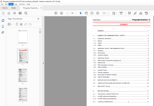
TABLE OF CONTENTS:
Pinguely Haulotte SELF PROPELLED LIFT HA20 PX - HA26PX REPAIR MANUAL - PDF DOWNLOAD
general 3
1 - general recommendations - safety 11
11 - general warning 11
111 - Manual 11
112 - Labels 11
113 - Safety 11
12 - general safety recommendations 12
121 - Operators 12
122 - Environment 12
123 - Using the machine 12
13 - RESIDUAL RISKS 14
131 - Risks of jerky movements and tipping over 14
132 - Electrical risk 14
133 - Risk of explosion or burning 14
134 - Risks of collision 14
14 - INSPECTIONS 15
141 - Periodic inspections 15
142 - Examination of machine suitability 15
143 - State of conservation 15
15 - REPAIRS AND ADJUSTMENTS 16
16 - Verifications When Returning To Service 16
17 - Beaufort Scale 16
2 - SPECIFICATIONS 17
21 - TECHNICAL CHARACTERISTICS 17
211 - HA 20PX technical characteristics 17
212 - HA 26PX technical characteristics 18
22 - OVERALL DIMENSIONS 20
221 - HA 20PX overall dimensions 20
222 - HA 26PX overall dimensions 21
23 - tightening torque 22
231 - Tightening torque for large thread 22
232 - Tightening torque for fine thread 22
233 - Tightening torque for hydraulic hoses 23
234 - Pressure values (in bar) 24
235 - Adjustment time 25
3 - SAFETY SYSTEM 27
31 - FUNCTIONS OF THE TURRET CABINET FUSES AND RELAYS 27
32 - FUNCTION OF THE SAFETY SWITCHES 27
4 - WIRING DIAGRAM 29
41 - WIRING DIAGRAM E 448 - Folio 01/05 29
42 - WIRING DIAGRAM E 448 - Folio 02/05 30
43 - WIRING DIAGRAM E 448 - Folio 03/05 31
44 - WIRING DIAGRAM E 448 - Folio 04/05 32
45 - WIRING DIAGRAM E 448 - Folio 05/05 33
46 - PART LIST 34
5 - MACHINES ELEMENTS 37
51 - MOTOR 37
52 - FUSES 37
53 - Input 37
531 - Control inputs : 37
532 - Safety inputs : 39
54 - Output 39
541 - Relay 39
542 - "On/Off" electrovalves 39
543 - Proportional electrovalves 40
544 - Buzzer and light indicators 40
6 - operating equations 41
61 - start 41
62 - Stop moteur 41
63 - accelerator 41
64 - Compensation 41
65 - Rotation 41
66 - jib 42
67 - rotation 42
68 - arm lifting 42
69 - boom lifting 43
610 - telescoping 43
611 - travel 43
612 - steering 43
613 - differential blocking 44
614 - horn - buzzer 44
615 - indicators 44
616 - OTHER FUNCTIONS : OVERLOAD, DEAD MAN, SLOPE 45
6161 - Overload 45
6162 - Dead man 45
6163 - Slope 45
617 - HA26P REACH LIMIT 45
7 - SAFETY LOCATION 47
8 - POSITIONs of electric components 49
81 - mother board 49
811 - Description 49
812 - Positions of screws, connectors and relays 50
813 - Positions of fuses 51
814 - Positions of diagnosis help LEDs 52
9 - HYDRAULIC DIAGRAMS 53
91 - hydraulic diagram for ha20/26px AND ha61/80jrt MODELS (B1539)0 53
10 - HYDRAULICS COMPONENTS DESCRIPTION 55
101 - tRAVEL BLOCK 55
1011 - Location 55
1012 - Input and output 57
102 - PVG 32 DANFOSS BLOCK 58
1021 - Location 58
1022 - Input and output 59
103 - CETOP 3 AUXOLIARY BLOCK 60
1031 - Location 60
104 - Emergency pump unit 61
1041 - Location 61
105 - telecoping block 62
1051 - Location 62
106 - steering block control 63
1061 - Location 63
1062 - Input and output 63
11 - HYDRAULIC EQUATIONS 65
111 - TRAVEL 65
112 - Turntable rotation 65
113 - arm lifting 65
114 - boom lifting 65
115 - Telescoping 65
116 - Other movement 65
12 - MAINTENANCE 67
121 - GENERAL RECOMMENDATIONS 67
122 - PARTICULAR RECOMMENDATIONS 67
1221 - Specific tools 67
1222 - Replacing an element 68
1223 - Locating the breakdown 68
123 - maintenance system 68
124 - electric power supply 69
125 - MAINTENANCE PLAN 70
126 - OPERATIONS 72
1261 - Summary table 72
127 - presence of labels 73
1271 - Common "yellow" label 73
1272 - Commom "orange" label 74
1273 - Common "red" label 75
1274 - Other common label 76
1275 - Model-specific labels 77
1276 - Description 78
1277 - Label positioning 79
128 - presence of manuals 80
13 - PREVENTIVE MAINTENANCE SHEET 81
14 - OPERATING INCIDENTS 89
141 - INCIDENT TABLE 89
1411 - General operation 90
1412 - Lifting system 92
1413 - Travel system 93
1414 - Steering system 94
1415 - Turntable rotation system 94
142 - breakdown detection flow chart 94
15 - CORRECTIVE MAINTENANCE PROCEDURES183
S.M 24/2/2025

