$29.95
Sakai Asphalt Roller CR271 Service Manual – PDF DOWNLOAD
Sakai Asphalt Roller CR271 Service Manual – PDF DOWNLOAD
The Sakai Asphalt Roller CR271 Service Manual in PDF format offers comprehensive guidance for maintenance, repair, and operation of the CR271 model, facilitating efficient servicing procedures and ensuring optimal performance.
FILE DETAILS:
Sakai Asphalt Roller CR271 Service Manual – PDF DOWNLOAD
Language : English
Pages : 170
Downloadable : Yes
File Type : PDF
IMAGES PREVIEW OF THE MANUAL:
DESCRIPTION:
Sakai Asphalt Roller CR271 Service Manual – PDF DOWNLOAD
- This manual provides important information to familiarize you with safe operating and maintenance procedures for your SAKAI roller. Even though you may be familiar with similar equipment you must read and understand this manual before operating or servicing this unit.
- Safety is everyone’s business and it is one of your primary concerns. Knowing the guidelines presented in this manual will help provide for your safety, for the safety of those around you and for the proper operation and maintenance of the machine. Improper operation is dangerous and can result in injury or death.
- Sakai Heavy Industries cannot foresee all possible circumstances or varying conditions to which the operator, serviceman or machine may be exposed to that might lead to a potential hazard. Therefore, the warnings and cautions listed in this manual and those placed on the machine are not intended to be all inclusive and liability for personal injury or damage to equipment or property cannot be assumed.
- All information, specifications and illustrations in this publication are based on the product information available at the time that the publication was written. The contents may change without prior notice due to modifications of the model.
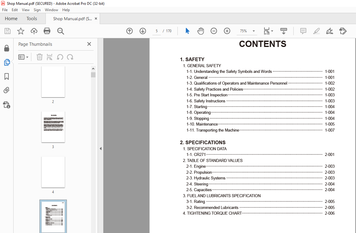
TABLE OF CONTENTS:
Sakai Asphalt Roller CR271 Service Manual – PDF DOWNLOAD
1. SAFETY
1. GENERAL SAFETY
1-1. Understanding the Safety Symbols and Words 1-001
1-2. General 1-001
1-3. Qualifications of Operators and Maintenance Personnel 1-002
1-4. Safety Practices and Policies 1-002
1-5. Pre Start Inspection 1-003
1-6. Safety Instructions 1-003
1-7. Starting 1-004
1-8. Operating 1-004
1-9. Stopping 1-004
1-10. Maintenance 1-005
1-11. Transporting the Machine 1-007
2. SPECIFICATIONS
1. SPECIFICATION DATA
1-1. CR271 2-001
2. TABLE OF STANDARD VALUES
2-1. Engine 2-003
2-2. Propulsion 2-003
2-3. Hydraulic Systems 2-003
2-4. Steering 2-004
2-5. Capacities 2-004
3. FUEL AND LUBRICANTS SPECIFICATION
3-1. Rating 2-005
3-2. Recommended Lubricants 2-005
4. TIGHTENING TORQUE CHART 2-006
CR271 ○0
3. ENGINE AND CONTROLS
1. ENGINE
1-1. Engine Mount 3-001
2. CONTROL SYSTEM
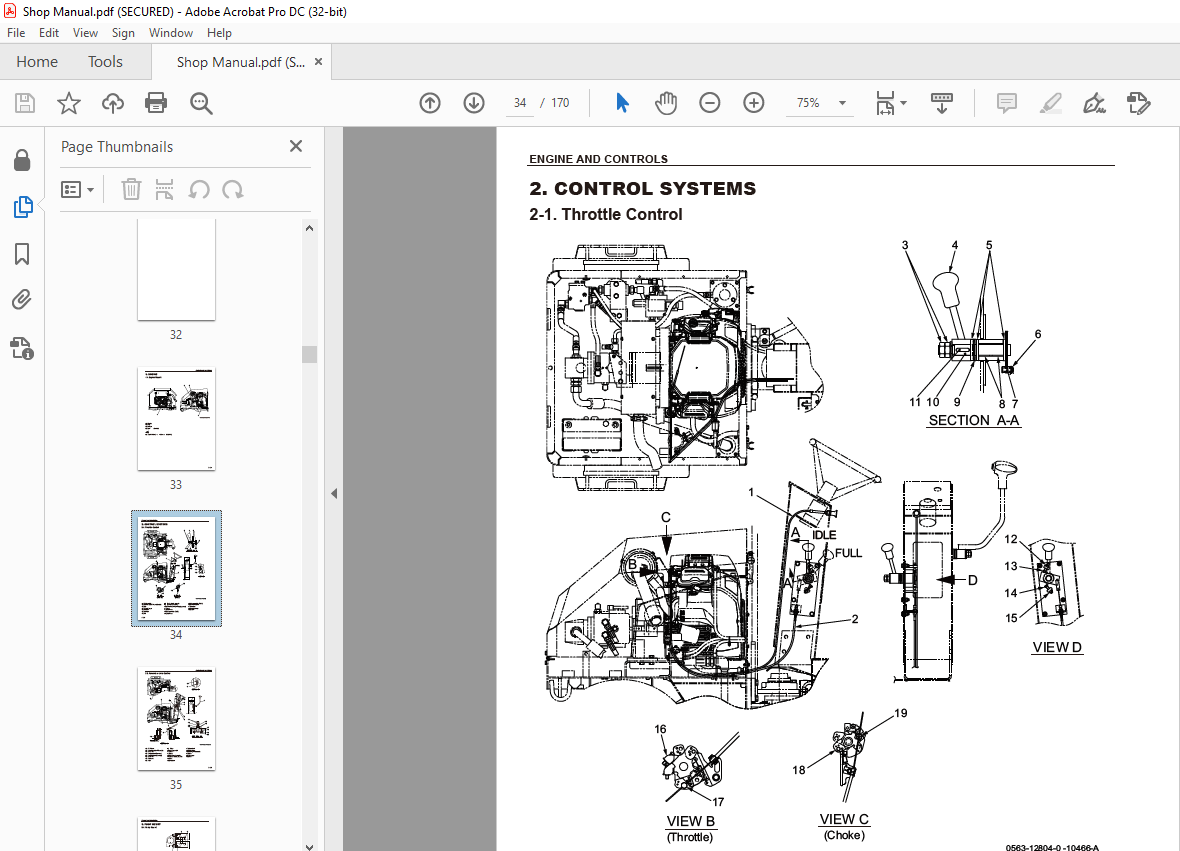
2-1. Throttle Control 3-002
2-2. Forward-reverse Control 3-003
3. PUMP MOUNT
3-1. Pump Mount 3-004
3-1-1. Installation of pump 3-005
4. HYDRAULIC SYSTEMS
1. SYSTEM CIRCUIT DIAGRAM
1-1. Graphic Symbols for Hydraulic Circuits 4-001
1-2. Hydraulic Circuit Diagram 4-003
2. PROPULSION HYDRAULIC SYSTEM
2-1. Propulsion Hydraulic Piping 4-004
2-1-1. Propulsion hydraulic piping (1) 4-004
2-1-2. Propulsion hydraulic piping (2) 4-005
2-2. Hydraulic Component Specifications 4-006
2-2-1. Hydraulic pump assembly (propulsion + vibrator + steering) 4-006
2-2-2. Propulsion hydraulic motor 4-008
2-2-3. Valve block 4-009
2-2-4. Valve 4-010
3. VIBRATOR HYDRAULIC SYSTEM
3-1. Vibrator Hydraulic Piping 4-011
3-2. Hydraulic Component Specification 4-012
3-2-1. Vibrator hydraulic motor 4-012
4. STEERING SYSTEM
4-1. Steering Hydraulic Piping 4-013
4-2. Hydraulic Component Specifications 4-014
4-2-1. Orbitrol 4-014
4-3. Frame (Center Pin) 4-015
CR271 ○0
5. ELECTRICAL SYSTEM
1. Precautions for wor k
1-1. W ire Numbers, Wire Sizes, Wire Colors and Connectors Shown in
Electrical Circuit Diagrams, Wiring Harness Layout and Wiring Harnesses 5-001
2. SYSTEM CIRCUIT DIAGRAM
2-1. Electrical Circuit Diagram 5-003
3. ELECTRICAL COMPONENTS
3-1. Electrical component Layout 5-004
4. WIRING HARNESSES
4-1. Harness (1) 5-005
4-2. Harness (2) 5-007
6. DRUMS
1. PRECAUTIONS FOR DISASSEMBLY AND REASSEMBLY 6-001
2. REMOVAL AND INSTALLATION OF DRUMS
2-1. Removal of Drums 6-003
2-1-1. Front drum 6-003
2-1-2. Rear drum 6-006
2-2. Installation of Drums 6-008
3. DRUM ASSEMBLY
3-1. Front Drum 6-009
3-2. Rear Drum 6-010
4. DISASSEMBLY AND REASSEMBLY OF DRUMS
4-1. Disassembly of Drums 6-011
4-1-1. Front drum 6-011
4-1-2. Rear drum 6-018
4-2. Reassembly of Drums 6-024
4-2-1. Front drum 6-024
4-2-2. Rear drum 6-034
7. PARKING BRAKE
1. PARKING BRAKE
1-1. Brake 7-001
8. WATER SPRAY SYSTEM
1. WATER SPRAY SYSTEM
1-1. Water spray 8-001
9. INSPECTION AND ADJUSTMENT
1. INSPECTION AND ADJUSTMENT
1-1. Safety Precautions for Inspection and Adjustment 9-001
1-2. Preparation for Inspection and Adjustment 9-001
1-3. Precautions for Inspection and Adjustment 9-001
1-4. Warm-up 9-001
1-5. Inspection and Adjustment of Engine Related Items 9-001
2. MEASUREMENT AND INSPECTION OF PROPULSION CIRCUIT PRESSURE
2-1. Measurement 9-002
2-2. Adjustment 9-003
3. MEASUREMENT AND INSPECTION OF PROPULSION CHARGE CIRCUIT
PRESSURE 9-004
3-1. Measurement 9-004
3-2. Adjustment 9-005
4. MEASUREMENT AND ADJUSTMENT OF STEERING CIRCUIT PRESSURE
4-1. Measurement 9-006
4-2. Adjustment 9-007
5. MEASUREMENT OF HYDRAULIC PUMP CASE PRESSURE
5-1. Measurement 9-008
6. MEASUREMENT OF PROPULSION MOTOR CASE PRESSURE
6-1. Measurement 9-009
7. ADJUSTMENT OF THROTTLE LEVER LINKAGE
7-1. Adjustment 9-010
8. ADJUSTMENT OF F-R LEVER LINKAGE
8-1. Adjustment 9-012
10. TROUBLESHOOTING
1. TROUBLESHOOTING
1-1. Safety Precautions for Troubleshooting 10-001
1-2. Important Information for Troubleshooting 10-001
1-3. Before Starting 10-002
1-4. Wire Number and Color Code 10-002
2. ELECTRICAL SYSTEM TROUBLESHOOTING
2-1. When Performing Electrical System Fault Diagnosis 10-003
2-1-1. Precautions to take during electrical circuit fault diagnosis 10-003
2-1-2. Inspection procedures using a tester 10-004
2-1-3. Inspection of electrical system 10-009
2-2. Engine 10-012
CR271 ○0
2-2-1. Engine will not start (Starter motor does not run) 10-012
2-2-2. Engine will not start (But starter motor runs) 10-014
2-2-3. No charging 10-016
2-2-4. Starter motor runs even when F-R lever is not at “N” applied 10-016
2-3. Propulsion 10-018
2-3-1. Hour meter is abnormal 10-018
2-3-2. Horn does not sound 10-018
2-4. Vibration 10-020
2-4-1. No vibration occurs 10-020
3. HYDRAULIC SYSTEM TROUBLESHOOTING
3-1. When Performing Hydraulic System Troubleshooting 10-021
3-2. Propulsion System 10-022
3-2-1. Machine moves neither forward nor backward 10-022
3-2-2. Machine moves in one direction only (forward or backward) 10-023
3-2-3. Slow machine speed or small drive force 10-023
3-2-4. Machine does not stop completely with F-R lever in “N” 10-024
3-2-5. Propulsion system is overheating 10-024
3-2-6. Abnormal noise from propulsion system 10-024
3-3. Steering System 10-025
3-3-1. Steering wheel is hard to turn 10-025
3-3-2. Steering response is slow 10-025
3-3-3. Steering wheel backlash or play is large 10-026
3-3-4. Steering system is overheating 10-026
3-3-5. Abnormal noise from steering system 10-026
More products