$37
Sakai Asphalt Roller GW754 Shop Manual – PDF DOWNLOAD
Sakai Asphalt Roller GW754 Shop Manual – PDF DOWNLOAD
The Sakai Asphalt Roller GW754 Shop Manual is a comprehensive guide in PDF format for maintenance, repair, and operation of the GW754 model. It includes detailed instructions, diagrams, and specifications, essential for efficient equipment management.
FILE DETAILS:
Sakai Asphalt Roller GW754 Shop Manual – PDF DOWNLOAD
Language : English
Pages : 384
Downloadable : Yes
File Type : PDF
IMAGES PREVIEW OF THE MANUAL:
DESCRIPTION:
Sakai Asphalt Roller GW754 Shop Manual – PDF DOWNLOAD
- This manual provides important information to familiarize you with safe operating and maintenance procedures for your SAKAI roller. Even though you may be familiar with similar equipment you must read and understand this manual before operating or servicing this unit.
- Safety is everyone’s business and it is one of your primary concerns. Knowing the guidelines presented in this manual will help provide for your safety, for the safety of those around you and for the proper operation and maintenance of the machine. Improper operation is dangerous and can result in injury or death.
- Sakai Heavy Industries cannot foresee all possible circumstances or varying conditions to which the operator, serviceman or machine may be exposed to that might lead to a potential hazard. Therefore, the warnings and cautions listed in this manual and those placed on the machine are not intended to be all inclusive and liability for personal injury or damage to equipment or property cannot be assumed.
- All information, specifications and illustrations in this publication are based on the product information available at the time that the publication was written. The contents may change without prior notice due to modifications of the model.
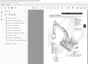
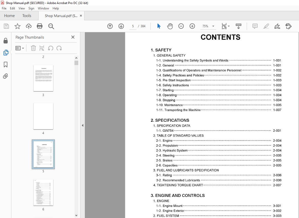
TABLE OF CONTENTS:
Sakai Asphalt Roller GW754 Shop Manual – PDF DOWNLOAD
1 SAFETY
1 GENERAL SAFETY
1-1 Understanding the Safety Symbols and Words 1-001
1-2 General 1-001
1-3 Qualifications of Operators and Maintenance Personnel 1-002
1-4 Safety Practices and Policies 1-002
1-5 Pre Start Inspection 1-003
1-6 Safety Instructions 1-003
1-7 Starting , 1-004
1-8 Operating 1-004
1-9 Stopping 1-004
1-10 Maintenance 1-005
1-11 Transporting the Machine 1-007
2 SPECIFICATIONS
1 SPECIFICATION DATA
1-1 GW754 2-001
2 TABLE OF STANDARD VALUES
2-1 Engine 2-004
2-2 Propulsion, 2-004
2-3 Hydraulic System 2-004
2-4 Steering 2-005
2-5 Brakes 2-005
2-6 Capacities 2-005
3 FU ELAND LUBRICANTS SPECIFICATION
3-1 Rating 2-006
3-2 Recommended Lubricants 2-006
4 TIGHTENING TORQUE CHART 2-007
3 ENGINE AND CONTROLS
1 ENGINE
1-1 Engine Mount 3-001
1-2 Engine Exterior 3-002
2 FUEL SYSTEM 3-003
3 EXHAUST SYSTEM
3-1 Exhaust System 3-005
3-1-1 DPF ASSY 3-006
3-1-2 SCR ASSY 3-007
3-2 Urea Piping 00
0000 3-008
3-2-1 DEF pump 3-009
3-2-2 DEF tank 3-010
4 CONTROL SYSTEM
4-1 Forward-reverse Control 3-011
4-1-1 Shift lever SU BASSY 00 3-012
5 PUMP MOUNT
5-1 Pump Mount, 3-013
5-1-1 Installation of pump 3-014
4 HYDRAULIC SYSTEMS
1 SYSTEM CIRCUIT DIAGRAM
1-1 Graphic Symbols for Hydraulic Circuits 4-001
1-2 Hydraulic Circuit Diagram, 4-003
2 PROPULSION HYDRAULIC SYSTEM
2-1 Propulsion Hydraulic Piping 4-004
2-1-1 Propulsion hydraulic piping (pump) 00
• 4-004
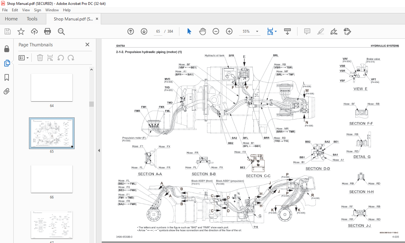
2-1-2 Propulsion hydraulic piping (motor) (1) 4-005
2-1-3 Propulsion hydraulic piping (motor) (2) 4-006
2-2 Hydraulic Component Specifications 4-007
2-2-1 Propulsion hydraulic pump 4-007
2-2-2 Propulsion hydraulic motor 4-008
2-2-3 Block ASSY (propulsion) 4-009
2-2-4 Block ASSY (front) 4-011
2-2-5 Servo bypass solenoid va Ive 4-012
2-2-6 Parking brake solenoid valve 4-013
2-2-7 Brake valve 4-014
2-3 Description and Operation of Propulsion System- 4-016
3 VIBRATOR HYDRAULIC SYSTEM
3-1 Vibrator Hydraulic Piping 4-019
3-1-1 Vibrator hydraulic piping (pump) 4-019
3-1-2 Vibrator hydraulic piping (motor) (1) 4-020
3-1-3 Vibrator hydraulic piping (motor) (2) 4-021
3-1-4 Amplitude cylinder piping (1) 4-022
3-1-5 Amplitude cylinder piping (2) 4-023
3-2 Hydraulic Component Specifications 4-024
3-2-1 Vibrator hydraulic pump 4-024
3-2-2 Vibrator hydraulic motor (F) 4-025
3-2-3 Vibrator hydraulic motor (R,L), (R,R)”‘””‘” 4-026
3-2-4 Valve block ASSY (amplitude) 4-027
3-2-5 Amplitude cylinder (F) 4-029
3-2-6 Amplitude cylinder (R, L), (R, R) 4-030
3-2-7 Vibrator solenoid valve (F), (R) 4-031
3-2-8 Flow divider 4-032
3-3 Description and Operation of Vibrator System 4-034
4 STEERING SYSTEM
4-1 Steering Hydraulic Piping 4-035
4-2 Steering VVheel 4-036
4-3 Hydraulic Component Specifications 4-037
4-3-1 Steering• charge pump 4-037
4-3-2 Orbitrol 4-038
4-4 Description and Operation of Steering System 4-040
4-4-1 Description and operation of steering system, 4-040
4-4-2 Structure and operation of Orbitrol 4-041
5 ELECTRICAL SYSTEM
1 PRECAUTIONS FOR WORK
1-1 Wre Numbers, Wre Sizes, Wre Colors and Connectors Shown in
Electrical Circuit Diagram, Wring Harness Layout and Wring Harnesses 5-001
2 SYSTEM CIRCUIT DIAGRAM
2-1 Electrical Circuit Diagram 5-003
3 ELECTRICAL COMPONENTS
3-1 VI/iring Harness Layout (1) 5-004
3-2 Wring Harness Layout (2) 5-005
3-3 Wring Harness Layout (3) 5-006
4 WIRING HARNESSES
4-1 Fuse• Relay Harness 5-007
4-2 Amplitude Cylinder Solenoid Harness 5-009
4-3 ECU Harness 5-011
4-4 ACU Harness 5-013
4-5 Dashboard Harness 5-015
4-6 Air Flow Sensor Harness 5-017
4-7 Battery Relay Harness 5-019
4-8 Member (F) Harness 5-020
4-9 Member (R) Harness 5-021
4-10 Battery Box Connect Harness 5-022
4-11 Engine Harness 5-023
4-12 Starter Switch Harness 5-024
4-13 Head Lamp Harness 5-025
4-14 F-R Lever Harness 5-026
4-15 F-R Lever Vibration Switch Harness 5-027
4-16 Amplitude Cylinder Switch Harness (F) 5-028
4-17 Amplitude Cylinder Switch Harness (R,L) 5-029
4-18 Amplitude Cylinder Switch Harness (R,R) 5-030
4-19 Waler Spray Pump Harness 5-031
4-20 Cord 5-032
4-21 Ground Cord 1 5-033
4-22 Ground Cord 2 5-034
4-23 Ground Cord 3 5-035
5 ELECTRICAL COMPONENT SPECIFICATIONS
5-1 Fuse Box 1 5-036
5-2 Fuse Box 2, 5-037
5-3 Combination Meter 5-038
6 WHEEL AND VIBRATOR SYSTEM
1 PRECAUTIONS FOR DISASSEMBLY AND REASSEMBLY 6-001
2 FRONT WHEEL
2-1 Removal and Installation of Front Wheel ASSY 6-003
2-1-1 Removal of front wheel ASSY 6-003
2-1-2 Installation of front wheel ASSY 6-006
2-2 Front Wheel ASSY 6-007
2-3 Disassembly and Reassembly of Front Wheel 6-008
2-3-1 Disassembly of front wheel 6-008
2-3-2 Reassembly of front wheel 6-017
3 REAR WHEEL
3-1 Removal and Installation of Rear Wheel ASSY 6-037
3-1-1 Removal ofrearwheelAssy 6-037
3-1-2 Installation of rear wheel ASSY 6-042
3-2 Rear Wheel ASSY 6-043
3-3 Disassembly and Reassembly of Rear Wheel 6-044
3-3-1 Disassembly of rear wheel 6-044
3-3-2 Reassembly of rear wheel 6-055
7 BRAKE
1 BRAKE PEDAL 7-001
2 BRAKE SYSTEM
2-1 Description and Operation of Brake Circuit 7-003
8 OPERATOR STATION
1 FLOORBOARD
1-1 Structure of Operator Station 8-001
1-2 Adjustment of Swivel Lock Release Pedal 8-002
9 WATER SPRAY SYSTEM
1 WATER SPRAY PIPING
1-1 \Nater Spray Piping (1) 9-001
1-2 \Nater Spray Piping (2) 9-002
2 LIQUID SPRAY SYSTEM
2-1 Liquid Spray Piping (1) 9-003
2-2 Liquid Spray Piping (2) 9-004
3 WATER SPRAY COMPONENT SPECIFICATIONS
3-1 Change Over Solenoid Valve 9-005
3-2 Liquid Spray Solenoid Valve (F), (R) 9-006
10 INSPECTION AND ADJUSTMENT
1 INSPECTION AND ADJUSTMENT
1-1 Safety Precautions for Inspection and Adjustment 10-001
1-2 Preparation for Inspection and Adjustment 10-001
1-3 Precautions for Inspection and Adjustment 10-001
1-4 \l\/arm-up 10-001
1-5 Inspection and Adjustment of Engine Related Items 10-001
2 MEASUREMENT AND INSPECTION OF PROPULSION CIRCUIT PRESSURE
2-1 Measurement 10-002
2-2 Inspection 10-003
3 MEASUREMENT AND ADJUSTMENT OF PROPULSION CHARGE CIRCUIT
PRESSURE
3-1 Measurement 10-004
3-2 Adjustment 10-005
4 MEASUREMENT AND ADJUSTMENT OF PROPULSION SERVO CIRCUIT
PRESSURE
4-1 Measurement 10-006
4-2 Adjustment 10-007
5 MEASUREMENT OF PARKING BRAKE RELEASE PRESSURE
5-1 Measurement 10-008
6 MEASUREMENT AND ADJUSTMENT OF VIBRATOR CIRCUIT PRESSURE
6-1 Measurement 10-009
6-2 Adjustment 10-010
7 MEASUREMENT AND INSPECTION OF STEERING CIRCUIT PRESSURE
7-1 Measurement 10-011
7-2 Inspection 10-012
8 ADJUSTMENT OF F-R LEVER AND SHIFT LEVER
8-1 Adjustment of Linkage 10-013
8-2 Adjustment of Operating Force 10-015
8-2-1 Adjustment of F-R lever 10-015
8-2-2 Adjustment of shift lever 10-016
11 TROUBLESHOOTING
1 TROUBLESHOOTING
1-1 Safety Precautions for Troubleshooting 11-001
1-2 Important Information for Troubleshooting 11-001
1-3 Before Starting 11-002
2 ELECTRICAL SYSTEM TROUBLESHOOTING
2-1 When Performing Electrical System Fault Diagnosis 11-003
2-1-1 Precautions to take during electrical circuit fault diagnosis 11-003
2-1-2 Inspection procedures using a tester 11-004
2-1-3 Inspection of electrical system 11-009
2-2 Engine Diagnosis Trouble Code 11-011
2-2-1 Description of fault code (SPN, FMI) 11-011
2-2-2 Fault code list (SPN, FM I) 11-012
2-3 Engine 11-021
2-3-1 Engine will not start (Starter motor does not run) 113 11-021
2-3-1 Engine will not start (Starter motor does not run) 2/3 11-023
2-3-1 Engine will not start (Starter motor does not run) 3/3 11-025
2-3-2 Engine will not start (But starter motor runs) 11-027
2-3-3 No charging 11-027
2-3-4 Intake heater is not heated
(Engine starting performance is bad in cold weather) 11-029
2-3-5 Starter motor runs even when F-R lever is not at “N” 11-029
2-3-6 Engine speed cannot be switched 11-029
2-4 Propulsion System 11-031
2-4-1 Machine moves neither forward nor backward 11-031
2-4-2 Brake cannot be released 11-033
2-4-3 Brake does not work 11-035
2-5 Vibration 11-037
2-5-1 No vibration occurs 1/2 11-037
2-5-1 No vibration occurs 2/2 11-039
2-5-2 Vibration amplitude does not change
(It vibrates at Amplitude 1, but vibration amplitude does not switch over
at Amplitude 2 to 4 positions) 1 /2 11-041
2-5-2 Vibration amplitude does not change
(It vibrates at Amplitude 1 but vibration amplitude does not switch over
at Amplitude 2 to 4 positions) 2/2 11-043
2-5-3 Vibration amplitude does not change
(The vibration amplitude switches only between the minimum
(Amplitude 1) and the maximum (Amplitude 4)) 1 /2 11-045
2-5-3 Vibration amplitude does not change
(The vibration amplitude switches only between the minimum
(Amplitude 1) and the maximum (Amplitude 4)) 2/2 11-047
2-5-4 Vibration mode cannot be switched
(F-R lever vibration switch does not work) 11-049
2-6 Water Spray 11-051
2-6-1 Continuous water spray does not operate 1/3 11-051
2-6-1 Continuous water spray does not operate 2/3 11-053
2-6-1 Continuous water spray does not operate 3/3 11-055
2-6-2 Continuous water spray works, but auto water spray does not operate 11-057
2-6-3 Continuous water spray works
but intermittent water spray does not operate 11-059
2-6-4 Water is not supplied from water spray tank (R) 11-061
2-6-5 Liquid cannot be sprayed 11-063
2-7 Lighting 11-065
2-7-1 Head lamp does not light 11-065
2-7-2 Flood lamp does not light 11-067
2-7-3 High-beam of head lamp does not light 11-067
2-7-4 Illumination of combination meter does not light 11-069
2-7-5 Combination meter warning lamp or indicator lamp is abnormal 11-069
2-7-6 Tachometer reading is abnormal 11-071
2-7-7 Hour meter is abnormal 11-071
2-7-8 Temperature meter is abnormal 11-073
2-7-9 Fuel meter is abnormal 11-073
2-7-10 Hydraulic oil filter warning lamp remains ON 11-075
2-7-11 Charge warning lamp remains ON 11-075
2-7-12 Water spray indicator lamp does not light 11-077
2-7-13 Liquid spray indicator lamp does not light 11-079
2-7-14 Flood lamp indicator lamp does not light 11-081
2-7-15 Parking brake indicator lamp does not light 11-081
2-7-16 Amplitude lamp (A) does not light 11-083
2-7-17 Amplitude lamp (B) does not light 11-085
2-7-18 Horn does not sound 11-087
2-7-19 Backup buzzer does not sound 11-087
3 HYDRAULIC SYSTEM TROUBLESHOOTING
3-1 When Performing Hydraulic System Troubleshooting 11-088
3-2 Propulsion System 11-089
3-2-1 Machine moves neither forward nor backward 1/2 11-089
3-2-1 Machine moves neither forward nor backward 2/2 11-090
3-2-2 Machine moves in one direction only (forward or backward) 11-090
3-2-3 Slow machine speed or small drive force 11-091
3-2-4 Machine does not stop completely with F-R lever in “N” 11-092
3-2-5 Propulsion system is overheating 11-092
3-2-6 Abnormal noise from propulsion system 11-092
3-3 Vibrator System 11-093
3-3-1 No vibration 11-093
3-3-2 Vibrator frequency is too low 11-094
3-3-3 Amplitude cannot be switched between high and low 11-094
3-3-4 Vibrator does not stop 11-095
3-3-5 Vibrator system is overheating 11-095
3-3-6 Abnormal noise from vibrator system 11-095
3-4 Steering System 11-096
3-4-1 Steering wheel is hard to turn 11-096
3-4-2 Steering response is slow 11-096
3-4-3 Steering wheel backlash or play is large 11-097
3-4-4 Steering system is overheating 11-097
3-4-5 Abnormal noise from steering system 11-097
3-5 Brake System 11-098
3-5-1 Parking brake does not operate 11-098
3-5-2 Brake cannot be released 11-098
More products