Starting from:
$28.95
Sakai Asphalt Roller R2-1 Series Service Manual - PDF
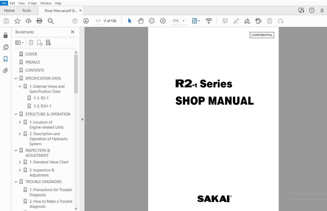
Sakai Asphalt Roller R2-1 Series Service Manual – PDF DOWNLOAD
The Sakai Asphalt Roller R2-1 Series Service Manual PDF is a comprehensive guide for maintenance and repair procedures for Sakai R2-1 asphalt rollers. It includes detailed instructions, diagrams, and specifications, essential for servicing these machines effectively.
FILE DETAILS:
Sakai Asphalt Roller R2-1 Series Service Manual – PDF DOWNLOAD
Language : English
Pages : 128
Downloadable : Yes
File Type : PDF
IMAGES PREVIEW OF THE MANUAL:
DESCRIPTION:
Sakai Asphalt Roller R2-1 Series Service Manual – PDF DOWNLOAD
- Performances of a vehicle will enevitablly fall with its component parts worn or deteriorated. To make a machine retain its original performances over a long operating hours without any troubles, correct handling and quality preventive maintenance are of vital importance. If a trouble occurs, its cause should be truck down as soon as practicable.
- This manual provides instructions on SPECIFICATIONS, STRUCTURE, OPERATION, INSPECTION, ADJUSTMENT and TROUBLE DIAGNOSIS of R2-1 Series Three-wheeled Rollers. For quick fault finding, this book uses diagnosis flow charts. Many diagnosis procedures are made available. Shown here represent typical examples. Other reasonable procedures will be usable. Depending upon conditions of troubles,the most suitable dignosis procedures should be used.
- The main purpose of this service literature is to serve as a guide for service personnel to acquire correct information on servicing the R2-1 Series Machines, passing a correct judgement on troubles, thus leading to quality servicing. Fully understand the instructions in this manual and make the best of it.
- We will make this book more substantial through repeated revisions. Your opinions and advices will be particularly welcome and carefully considered. For daily maintenance and periodical service schedule, refer to Operator’s Instructions furnished separately.
TABLE OF CONTENTS:
Sakai Asphalt Roller R2-1 Series Service Manual – PDF DOWNLOAD
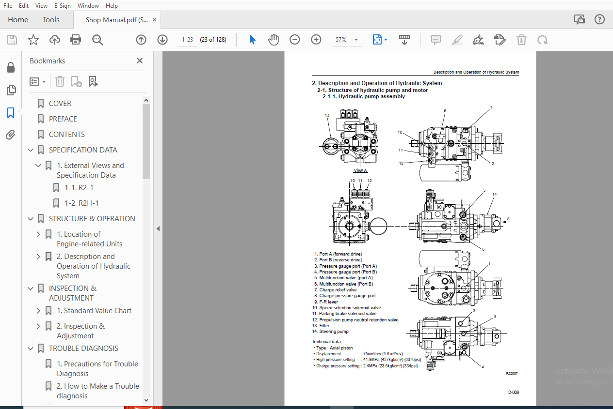
COVER....................................................................................................................................................................  1
PREFACE..................................................................................................................................................................  2
CONTENTS.................................................................................................................................................................  4
SPECIFICATION DATA.......................................................................................................................................................  7
	1. External Views and Specification Data.............................................................................................................................  8
		1-1. R2-1........................................................................................................................................................  8
		1-2. R2H-1....................................................................................................................................................... 10
STRUCTURE & OPERATION.................................................................................................................................................... 15
	1. Location of Engine-related Units.................................................................................................................................. 17
		1-1. Engine mount................................................................................................................................................ 17
		1-2. Intake system............................................................................................................................................... 18
		1-3. Exhaust system.............................................................................................................................................. 19
		1-4. Coolant line & radiator..................................................................................................................................... 20
		1-5. Fuel line & fuel tank....................................................................................................................................... 21
		1-6. Fuel controls............................................................................................................................................... 22
	2. Description and Operation of Hydraulic System..................................................................................................................... 23
		2-1. Structure of hydraulic pump and motor....................................................................................................................... 23
			2-1-1. Hydraulic pump assembly............................................................................................................................... 23
			2-1-2. Propulsion motor (Front).............................................................................................................................. 24
			2-1-3. Propulsion motor (Rear)............................................................................................................................... 26
			2-1-4. Coupling.............................................................................................................................................. 28
			2-1-5. Hydraulic circuit diagram............................................................................................................................. 29
		2-2. Drive line.................................................................................................................................................. 31
			2-2-1. Hydraulic line [1] (Front drum)....................................................................................................................... 31
			2-2-2. Hydraucic line [2] (Front drum)....................................................................................................................... 32
			2-2-3. Hydraulic line [3] (Rear single drum)................................................................................................................. 33
			2-2-4. Hydraulic line [4] (Rear split drum).................................................................................................................. 34
			2-2-5. Front drum............................................................................................................................................ 35
			2-2-6. Rear drum (Single drum)............................................................................................................................... 36
			2-2-7. Rear drum (Split drum)................................................................................................................................ 37
			2-2-8. Propulsion controls................................................................................................................................... 38
			2-2-9. Hydraulic circuit diagram for propulsion.............................................................................................................. 39
			2-2-10. Description and operation of drive line.............................................................................................................. 40
		3. Steering System............................................................................................................................................... 42
			3-1. Steering wheel.......................................................................................................................................... 42
			3-2. Center pin (King pin)................................................................................................................................... 43
			3-3. Steering valve (Orbitrol)............................................................................................................................... 44
			3-4. Description and operation of steering valve (Orbitrol).................................................................................................. 45
			3-5. Steering cylinder....................................................................................................................................... 49
			3-6. Hydraulic line.......................................................................................................................................... 50
			3-7. Hdraulic circuit diagram for steering................................................................................................................... 51
			3-8. Description and operation of steering system............................................................................................................ 52
		4. Brake System.................................................................................................................................................. 53
			4-1. Brake pedal & linkage................................................................................................................................... 53
			4-2. Description and operation of brake system............................................................................................................... 54
		5. Sprinkler & Scraper........................................................................................................................................... 55
			5-1.Sprinkler line........................................................................................................................................... 55
			5-2. Scraper (Front drum).................................................................................................................................... 56
			5-3. Scraper (Rear drum)..................................................................................................................................... 57
		6. Electric System............................................................................................................................................... 58
			6-1. Location of electric components (Panel・Relays).......................................................................................................... 58
			6-2. Location of electric components (Lamps)................................................................................................................. 59
			6-3.Electric wiring diagram.................................................................................................................................. 61
INSPECTION & ADJUSTMENT.................................................................................................................................................. 65
	1. Standard Value Chart.............................................................................................................................................. 66
		1-1. Standard value chart for machine body....................................................................................................................... 66
	2. Inspection & Adjustment........................................................................................................................................... 67
		2-1. Measurement and adjustment of pressure in propulsion main circuit........................................................................................... 67
		2-2. Measurement of propulsion charge pressure................................................................................................................... 69
		2-3. Measurement of pressure in propulsion motor speed selection circuit......................................................................................... 70
		2-4. Measurement of pressure in parking brake release circuit.................................................................................................... 71
		2-5. Measurement and adjustment of pressure in steering circuit.................................................................................................. 72
		2-6.Throttle linkage adjustment.................................................................................................................................. 73
		2-7.F-R lever linkage adjustment................................................................................................................................. 74
TROUBLE DIAGNOSIS........................................................................................................................................................ 77
	1. Precautions for Trouble Diagnosis................................................................................................................................. 78
	2. How to Make a Trouble diagnosis................................................................................................................................... 79
	3. How to Use Trouble Diagnosis Flow Chart........................................................................................................................... 80
	4. Precautions for Trouble Diagnosis of Electric System.............................................................................................................. 82
	5. Trouble Diagnosis of Electric System (Mode E)..................................................................................................................... 83
		E-01 Engine does not start....................................................................................................................................... 84
		E-02 Engine is not shut down..................................................................................................................................... 88
		E-03 Glow plugs do not become red-hot
(Engine is hard to start).................................................................................................. 89
		E-04 No charging (Charge indicator lamp stays bright)............................................................................................................ 92
		E-05 Backup buzzer does not sound or backup lamps do not come on................................................................................................. 93
		E-06 Horn does not sound......................................................................................................................................... 94
		E-07 Turn signal lamps do not come on............................................................................................................................ 95
		E-08 Headlamps, side marker lamps and tale lamps do not light.................................................................................................... 97
		E-09 Stop lamps do not light..................................................................................................................................... 99
		E-10 Flood lamps do not light....................................................................................................................................100
		E-11 Propulsion pump neutral retention valve is at fault.........................................................................................................101
		E-12 Poor parking brake function.................................................................................................................................102
		E-13 Timer sprinkling not selected...............................................................................................................................103
		E-14 Low-High speed range not selected...........................................................................................................................105
		E-15 Fuel gauge reads wrong......................................................................................................................................106
		E-16 Coolant temperature gauge reads wrong.......................................................................................................................107
		E-17 Tachometer reads wrong......................................................................................................................................108
		E-18 Charge lamp, engine oil pressure warning lamp, hydraulic oil filter
warning lamp and parking brake indicator lamp do not come on with
starter switch ON.....109
	6. Trouble Diagnosis of Hydraulic and Mechanical Systems (Mode H)....................................................................................................111
		Mechanical system diagnosis mode and units with possible source of trouble.......................................................................................112
		H-01 Unusual sounds..............................................................................................................................................114
		H-02 Hot hydraulic oil...........................................................................................................................................115
		H-03 Not propelled...............................................................................................................................................116
		H-04 Travel speed not gained or low traction.....................................................................................................................120
		H-05 Speed range not selected....................................................................................................................................124
		H-06 Steering not achieved.......................................................................................................................................124
		H-07 Heavy or slow steering......................................................................................................................................125
		H-08 Poor parking brake function.................................................................................................................................125
		H-09 Parking brake not released..................................................................................................................................126
		H-10 Timer sprinkling not selected...............................................................................................................................126
SAKAI HEAVY INDUSTRIES, LTD..............................................................................................................................................128
More products