$33
Sakai Asphalt Roller R2-4 Service Manual – PDF DOWNLOAD
Sakai Asphalt Roller R2-4 Service Manual – PDF DOWNLOAD
The Sakai Asphalt Roller R2-4 Service Manual PDF provides comprehensive guidance for maintenance and repair of the R2-4 model, aiding operators in maximizing efficiency and longevity of their equipment.
FILE DETAILS:
Sakai Asphalt Roller R2-4 Service Manual – PDF DOWNLOAD
Language : English
Pages : 234
Downloadable : Yes
File Type : PDF
IMAGES PREVIEW OF THE MANUAL:
DESCRIPTION:
Sakai Asphalt Roller R2-4 Service Manual – PDF DOWNLOAD
- This manual provides important information to familiarize you with safe operating and maintenance procedures for your SAKAI roller. Even though you may be familiar with similar equipment you must read and understand this manual before operating or servicing this unit.
- Safety is everyone’s business and it is one of your primary concerns. Knowing the guidelines presented in this manual will help provide for your safety, for the safety of those around you and for the proper operation and maintenance of the machine. Improper operation is dangerous and can result in injury or death.
- Sakai Heavy Industries cannot foresee all possible circumstances or varying conditions to which the operator, serviceman or machine may be exposed to that might lead to a potential hazard. Therefore, the warnings and cautions listed in this manual and those placed on the machine are not intended to be all inclusive and liability for personal injury or damage to equipment or property cannot be assumed.
- All information, specifications and illustrations in this publication are based on the product information available at the time that the publication was written. The contents may change without prior notice due to modifications of the model.
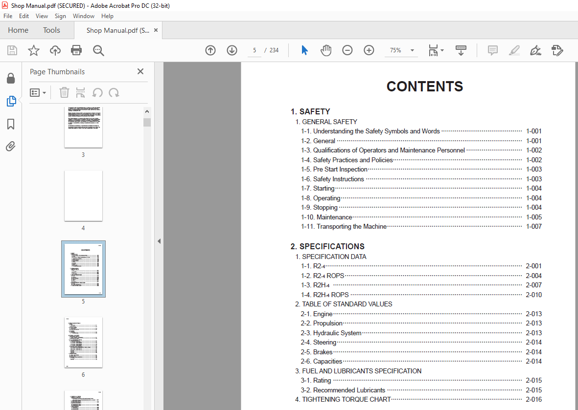
TABLE OF CONTENTS:
Sakai Asphalt Roller R2-4 Service Manual – PDF DOWNLOAD
1. SAFETY
1. GENERAL SAFETY
1-1. Understanding the Safety Symbols and Words 1-001
1-2. General 1-001
1-3. Qualifications of Operators and Maintenance Personnel 1-002
1-4. Safety Practices and Policies 1-002
1-5. Pre Start Inspection 1-003
1-6. Safety Instructions 1-003
1-7. Starting 1-004
1-8. Operating 1-004
1-9. Stopping 1-004
1-10. Maintenance 1-005
1-11. Transporting the Machine 1-007
2. SPECIFICATIONS
1. SPECIFICATION DATA
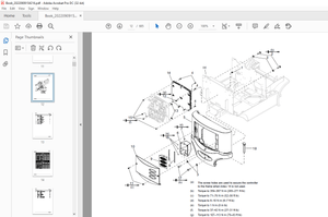
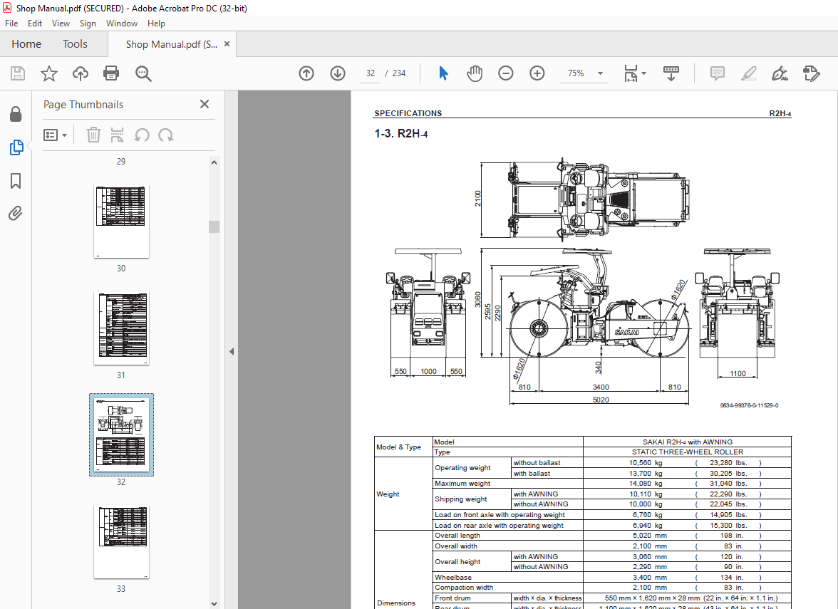
1-1. R2-4 2-001
1-2. R2-4 ROPS 2-004
1-3. R2H-4 2-007
1-4. R2H-4 ROPS 2-010
2. TABLE OF STANDARD VALUES
2-1. Engine 2-013
2-2. Propulsion 2-013
2-3. Hydraulic System 2-013
2-4. Steering 2-014
2-5. Brakes 2-014
2-6. Capacities 2-014
3. FUEL AND LUBRICANTS SPECIFICATION
3-1. Rating 2-015
3-2. Recommended Lubricants 2-015
4. TIGHTENING TORQUE CHART 2-016
R2-4 ○0
0-002
3. ENGINE AND CONTROLS
1. ENGINE
1-1. Engine Mount 3-001
1-2. Engine Exterior 3-002
2. CONTROL SYSTEMS
2-1. Throttle Control 3-003
2-2. Forward-reverse Control 3-004
3. PUMP MOUNT
3-1. Pump Mount 3-005
3-1-1. Installation of pump 3-006
4. HYDRAULIC SYSTEMS
1. SYSTEM CIRCUIT DIAGRAM
1-1. Graphic Symbols for Hydraulic Circuits 4-001
1-2. Hydraulic Circuit Diagram 4-003
2. PROPULSION HYDRAULIC SYSTEM
2-1. Propulsion Hydraulic Piping 4-004
2-1-1. Propulsion hydraulic piping (1) 4-004
2-1-2. Propulsion hydraulic piping (2) 4-005
2-1-3. Propulsion hydraulic piping (3) 4-006
2-1-4. Propulsion hydraulic piping (R) 4-007
2-2. Hydraulic Component Specifications 4-008
2-2-1. Hydraulic pump assembly (propulsion + steering・charge) 4-008
2-2-2. Propulsion hydraulic motor (F) 4-010
2-2-3. Propulsion hydraulic motor (R) 4-012
2-2-4. Valve 4-014
2-2-5. Block A 4-015
2-2-6. Block B 4-016
3. STEERING SYSTEM
3-1. Steering Hydraulic Piping 4-017
3-2. Steering Wheel 4-018
3-3. Hydraulic Component Specifications 4-019
3-3-1. Orbitrol 4-019
3-3-2. Valve 4-020
R2-4 ○0
0-003
5. ELECTRICAL SYSTEM
1. Precautions for wor k
1-1. Wire Numbers, Wire Sizes, Wire Colors and Connectors Shown in
Electrical Circuit Diagram, Wiring Harness Layout and Wiring Harnesses 5-001
2. SYSTEM CIRCUIT DIAGRAM
2-1. Electrical Circuit Diagram 5-003
3. ELECTRICAL COMPONENTS
3-1. Wiring Harness Layout (1) 5-004
3-2. Wiring Harness Layout (2) 5-005
4. WIRING HARNESSES
4-1. Main Harness (1) 5-006
4-2. Main Harness (2) 5-008
4-3. Main Harness (3) 5-010
4-4. Frame Harness (F) 5-012
4-5. Frame Harness (R) 5-014
4-6. Floor Board Harness 5-016
4-7. Engine Harness 5-018
4-8. Starter Switch Harness 5-019
4-9. Control Switch Harness 5-020
4-10. Lighting Switch Harness 5-021
4-11. Hazard Switch Harness 5-022
4-12. F-R Lever Switch Harness 5-023
4-13. Backup Buzzer Switch Harness 5-024
4-14. Foot Brake Switch Harness 5-025
4-15. ENGINE WARNING Lamp Harness 5-026
4-16. DPF Harness 5-027
4-17. Water Spray Harness 5-028
4-18. Combination Lamp Harness (F,L) 5-029
4-19. Combination Lamp Harness (F,R) 5-030
4-20. Sub Power Harness 5-031
5. ELECTRICAL COMPONENT SPECIFICATIONS
5-1. Fuse Box 5-032
5-2. Combination Meter 5-033
6. DRUM
1. PRECAUTIONS FOR DISASSEMBLY AND REASSEMBLY 6-001
2. DRUM
2-1. Drum (F) (R2-4) 6-003
2-2. Drum (F) (R2H-4) 6-004
R2-4 ○0
0-004
2-3. Drum (R) (R2-4) 6-005
2-4. Drum (R) (R2H-4) 6-006
7. BRAKE
1. BRAKE PEDAL 7-001
2. BRAKE SYSTEM 7-002
8. WATER SPRAY SYSTEM
1. WATER SPRAY PIPING 8-001
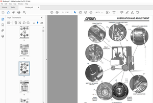
9. INSPECTION AND ADJUSTMENT
1. INSPECTION AND ADJUSTMENT
1-1. Safety Precautions for Inspection and Adjustment 9-001
1-2. Preparation for Inspection and Adjustment 9-001
1-3. Precautions for Inspection and Adjustment 9-001
1-4. Warm-up 9-001
1-5. Inspection and Adjustment of Engine Related Items 9-001
2. MEASUREMENT AND ADJUSTMENT OF PROPULSION CIRCUIT PRESSURE
2-1. Measurement 9-002
2-2. Adjustment 9-003
3. MEASUREMENT AND ADJUSTMENT OF PROPULSION CHARGE
CIRCUIT PRESSURE
3-1. Measurement 9-004
3-2. Adjustment 9-005
4. MEASUREMENT OF PROPULSION SERVO CIRCUIT PRESSURE
4-1. Measurement 9-006
5. MEASUREMENT OF MACHINE HIGH/LOW SPEED CHANGE CIRCUIT PRESSURE
5-1. Measurement 9-007
6. MEASUREMENT OF PARKING BRAKE RELEASE PRESSURE
6-1. Measurement of propulsion motor (F) 9-008
6-2. Measurement of propulsion motor (R) 9-009
7. MEASUREMENT AND INSPECTION OF STEERING CIRCUIT PRESSURE
7-1. Measurement 9-010
7-2. Inspection 9-011
8. MEASUREMENT OF HYDRAULIC PUMP CASE PRESSURE
8-1. Measurement of Propulsion Pump Case Pressure 9-012
9. MEASUREMENT OF PROPULSION MOTOR CASE PRESSURE
9-1. Measurement of Propulsion Motor (F) 9-013
9-2. Measurement of Propulsion Motor (R) 9-014
R2-4 ○0
0-005
10. ADJUSTMENT OF THROTTLE LEVER
10-1. Adjustment of Potentiometer 9-015
10-2. Adjustment of Operating Force 9-017
11. ADJUSTMENT OF F-R LEVER LINKAGE
11-1. Adjustment 9-018
10. TROUBLESHOOTING
1. TROUBLESHOOTING
1-1. Safety Precautions for Troubleshooting 10-001
1-2. Important Information for Troubleshooting 10-001
1-3. Before Starting 10-002
2. ELECTRICAL SYSTEM TROUBLESHOOTING
2-1. When Performing Electrical System Fault Diagnosis 10-003
2-1-1. Precautions to take during electrical circuit fault diagnosis 10-003
2-1-2. Inspection procedures using a tester 10-004
2-1-3. Inspection of electrical system 10-009
2-2. Engine Diagnosis Trouble Code 10-011
2-2-1. Description of diagnostic trouble code (DTC) 10-011
2-2-2. Table of the diagnostic trouble code (DTC) 10-012
2-3. Engine 10-019
2-3-1. Engine will not start (Starter motor does not run) 1/2 10-019
2-3-1. Engine will not start (Starter motor does not run) 2/2 10-021
2-3-2. Engine will not start (But starter motor runs) 10-023
2-3-3. No charging 10-023
2-3-4. Glow plug is not heated
(Engine starting performance is bad in cold weather) 10-025
2-3-5. Starter motor runs even when F-R lever is not at “N”
and parking brake is not applied 10-025
2-3-6. Engine speed does not change when operating throttle lever 10-027
2-4. Propulsion System 10-029
2-4-1. Machine moves neither forward nor backward 1/2 10-029
2-4-1. Machine moves neither forward nor backward 2/2 10-031
2-4-2. Brake cannot be released 10-031
2-4-3. Brake does not work 1/2 10-031
2-4-3. Brake does not work 2/2 10-033
2-4-4. Speed cannot be changed 10-033
2-5. Water Spray 10-035
2-5-1. Continuous water spray does not operate 10-035
2-5-2. Continuous water spray works, but intermittent water spray
does not operate 10-037
2-6. Lighting 10-039
2-6-1. Head lamp, side marker lamp, tail lamp and license lamp
do not light 1/2 10-039
2-6-1. Head lamp, side marker lamp, tail lamp and license lamp
do not light 2/2 10-041
2-6-2. Flood lamp does not light 1/2 10-041
2-6-2. Flood lamp does not light 2/2 10-043
2-6-3. High-beam of head lamp does not light 10-043
2-6-4. Turn signal lamp does not blink 10-045
2-6-5. Hazard lamp does not light (Turn signal blinks) 10-047
2-6-6. Backup lamp does not light 10-047
2-6-7. Stop lamp does not light 10-049
2-6-8. Illumination of combination meter does not light 10-051
2-6-9. Combination meter warning lamp or indicator lamp is abnormal 10-051
2-6-10. Tachometer reading is abnormal 10-053
2-6-11. Hour meter is abnormal 10-053
2-6-12. Temperature meter is abnormal 10-055
2-6-13. Fuel meter is abnormal 10-055
2-6-14. Charge warning lamp remains ON 10-057
2-6-15. Water spray indicator lamp does not light 10-057
2-6-16. Flood lamp indicator lamp does not light 10-059
2-6-17. Side marker lamp indicator lamp does not light 10-059
2-6-18. Parking brake indicator lamp does not light 10-061
2-6-19. Turn signal indicator lamp does not light 10-063
2-6-20. Horn does not sound 10-065
2-6-21. Backup buzzer does not sound 10-065
3. HYDRAULIC SYSTEM TROUBLESHOOTING
3-1. When Performing Hydraulic System Troubleshooting 10-066
3-2. Propulsion System 10-067
3-2-1. Machine moves neither forward nor backward 1/2 10-067
3-2-1. Machine moves neither forward nor backward 2/2 10-068
3-2-2. Machine moves in one direction only (forward or backward) 10-068
3-2-3. Slow machine speed or small drive force 1/2 10-068
3-2-3. Slow machine speed or small drive force 2/2 10-069
3-2-4. Machine speed cannot be switched 10-069
3-2-5. Machine does not stop completely with F-R lever in “N” 10-069
3-2-6. Propulsion system is overheating 10-070
3-2-7. Abnormal noise from propulsion system 10-070
R2-4 ○0
0-007
3-3. Steering System 10-071
3-3-1. Steering wheel is hard to turn 10-071
3-3-2. Steering response is slow 10-071
3-3-3. Steering wheel backlash or play is large 10-072
3-3-4. Steering system is overheating 10-072
3-3-5. Abnormal noise from steering system 10-072
More products