$35.95
Sakai Asphalt Roller SW/TW354 SW/TW504 Service Manual PDF
Sakai Asphalt Roller SW/TW354 SW/TW504 Service Manual – PDF DOWNLOAD
The Sakai Asphalt Roller SW/TW354 SW/TW504 Service Manual is a comprehensive guide in PDF format for maintenance and repair procedures of these specific models, aiding users in efficient upkeep and troubleshooting of their asphalt rollers.
FILE DETAILS:
Sakai Asphalt Roller SW/TW354 SW/TW504 Service Manual – PDF DOWNLOAD
Language : English
Pages : 480
Downloadable : Yes
File Type : PDF
IMAGES PREVIEW OF THE MANUAL:
DESCRIPTION:
Sakai Asphalt Roller SW/TW354 SW/TW504 Service Manual – PDF DOWNLOAD
- This manual provides important information to familiarize you with safe operating and maintenance procedures for your SAKAI roller. Even though you may be familiar with similar equipment you must read and understand this manual before operating or servicing this unit.
- Safety is everyone’s business and it is one of your primary concerns. Knowing the guidelines presented in this manual will help provide for your safety, for the safety of those around you and for the proper operation and maintenance of the machine. Improper operation is dangerous and can result in injury or death.
- Sakai Heavy Industries cannot foresee all possible circumstances or varying conditions to which the operator, serviceman or machine may be exposed to that might lead to a potential hazard. Therefore, the warnings and cautions listed in this manual and those placed on the machine are not intended to be all inclusive and liability for personal injury or damage to equipment or property cannot be assumed.
- All information, specifications and illustrations in this publication are based on the product information available at the time that the publication was written. The contents may change without prior notice due to modifications of the model.
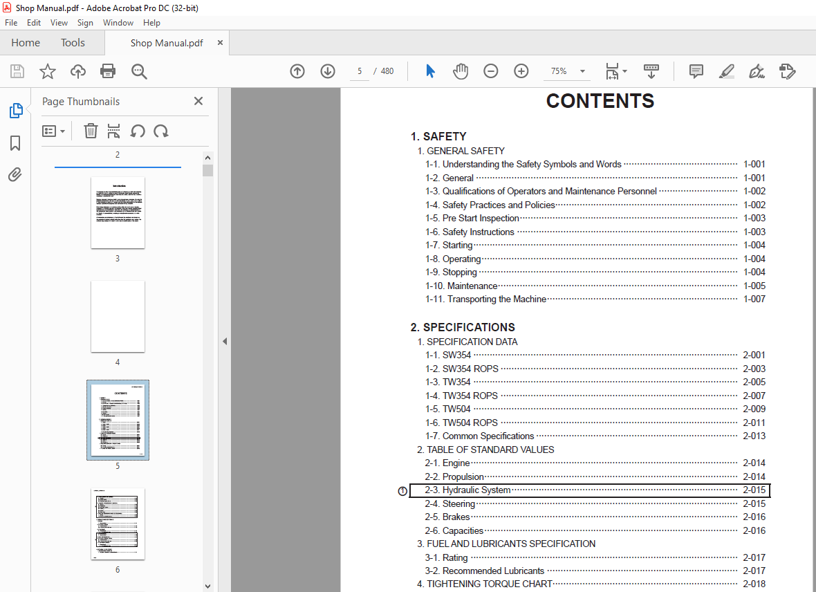
TABLE OF CONTENTS:
Sakai Asphalt Roller SW/TW354 SW/TW504 Service Manual – PDF DOWNLOAD
1. SAFETY
1. GENERAL SAFETY
1-1. Understanding the Safety Symbols and Words 1-001
1-2. General 1-001
1-3. Qualifications of Operators and Maintenance Personnel 1-002
1-4. Safety Practices and Policies 1-002
1-5. Pre Start Inspection 1-003
1-6. Safety Instructions 1-003
1-7. Starting 1-004
1-8. Operating 1-004
1-9. Stopping 1-004
1-10. Maintenance 1-005
1-11. Transporting the Machine 1-007
2. SPECIFICATIONS
1. SPECIFICATION DATA
1-1. SW354 2-001
1-2. SW354 ROPS 2-003
1-3. TW354 2-005
1-4. TW354 ROPS 2-007
1-5. TW504 2-009
1-6. TW504 ROPS 2-011
1-7. Common Specifications 2-013
2. TABLE OF STANDARD VALUES
2-1. Engine 2-014
2-2. Propulsion 2-014
2-3. Hydraulic System 2-015
2-4. Steering 2-015
2-5. Brakes 2-016
2-6. Capacities 2-016
3. FUEL AND LUBRICANTS SPECIFICATION
3-1. Rating 2-017
3-2. Recommended Lubricants 2-017
4. TIGHTENING TORQUE CHART 2-018
5. SPECIFICATION DATA (SW504)
5-1. SW504 2-019
5-2. SW504 ROPS 2-021
5-3. Common Specifications 2-023
6. TABLE OF STANDARD VALUES (SW504)
6-1. Engine 2-024
6-2. Propulsion 2-024
6-3. Hydraulic System 2-024
6-4. Steering 2-025
6-5. Brakes 2-025
6-6. Capacities 2-025
7. FUEL AND LUBRICANTS SPECIFICATION (SW504)
7-1. Rating 2-026
7-2. Recommended Lubricants 2-026
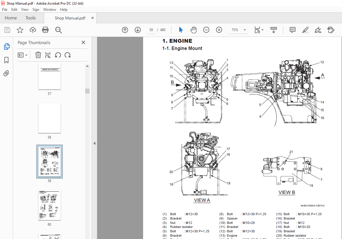
4. ENGINE AND CONTROLS
1. ENGINE
1-1. Engine Mount 3-001
2. CONTROL SYSTEM
2-1. Throttle Control 3-002
2-2. Forward-reverse Control 3-003
3. PUMP MOUNT
3-1. Pump Mount 3-004
3-1-1. Installation of pump 3-005
4. ENGINE (SW504)
4-1. Engine Mount 3-006
5. FUEL SYSTEM (SW504) 3-007
6. CONTROL SYSTEM (SW504)
6-1. Throttle Control 3-009
6-2. Forward-reverse Control 3-010
7. PUMP MOUNT (SW504)
7-1. Pump Mount 3-011
7-1-1. Installation of pump 3-012
5. HYDRAULIC SYSTEMS
1. SYSTEM CIRCUIT DIAGRAM
1-1. Graphic Symbols for Hydraulic Circuits 4-001
1-2. Hydraulic Circuit Diagram 4-003
1-2-1. Hydraulic circuit diagram (SW354) 4-003
1-2-2. Hydraulic circuit diagram (TW354) 4-004
1-2-3. Hydraulic circuit diagram (TW504) 4-005
2. PROPULSION HYDRAULIC SYSTEM
2-1. Propulsion Hydraulic Piping 4-006
2-1-1. Propulsion hydraulic piping (F) (SW/TW354) 4-006
2-1-2. Propulsion hydraulic piping (F) (TW504) 4-007
2-1-3. Propulsion hydraulic piping (R) (SW/TW354) 4-008
2-1-4. Propulsion hydraulic piping (R) (TW504) 4-009
2-2. Control Valve 4-010
2-3. Hydraulic Motor 4-011
3. STEERING HYDRAULIC SYSTEM
3-1. Steering Hydraulic Piping 4-012
3-2. Steering Priority Valve 4-013
3-3. Flow Divider Valve 4-013
3-4. Steering Cylinder 4-014
4. WORK EQUIPMENT HYDRAULIC SYSTEM
4-1. Work Equipment Hydraulic Piping 4-015
4-2. Arm Cylinder 4-016
4-3. Bucket Cylinder 4-017
5. HYDRAULIC SYSTEM (SW504)
5-1. System Circuit Diagram 4-018
5-2. Propulsion Hydraulic System 4-019
5-3. Steering Hydraulic System 4-021
5-4. Work Equipment Hydraulic System 4-022
More products