$35.95
Sakai Asphalt Roller SW880 SW990 Service Manual – PDF DOWNLOAD
Sakai Asphalt Roller SW880 SW990 Service Manual – PDF DOWNLOAD
The Sakai Asphalt Roller SW880 SW990 Service Manual PDF provides comprehensive guidance for maintenance, repair, and troubleshooting of these models, ensuring optimal performance and longevity.
FILE DETAILS:
Sakai Asphalt Roller SW880 SW990 Service Manual – PDF DOWNLOAD
Language : English
Pages : 354
Downloadable : Yes
File Type : PDF
IMAGES PREVIEW OF THE MANUAL:
DESCRIPTION:
Sakai Asphalt Roller SW880 SW990 Service Manual – PDF DOWNLOAD
- This manual provides important information to familiarize you with safe operating and maintenance procedures for your SAKAI roller. Even though you may be familiar with similar equipment you must read and understand this manual before operating or servicing this unit.
- Safety is everyone’s business and it is one of your primary concerns. Knowing the guidelines presented in this manual will help provide for your safety, for the safety of those around you and for the proper operation and maintenance of the machine. Improper operation is dangerous and can result in injury or death.
- Sakai Heavy Industries cannot foresee all possible circumstances or varying conditions to which the operator, serviceman or machine may be exposed to that might lead to a potential hazard. Therefore, the warnings and cautions listed in this manual and those placed on the machine are not intended to be all inclusive and liability for personal injury or damage to equipment or property cannot be assumed.
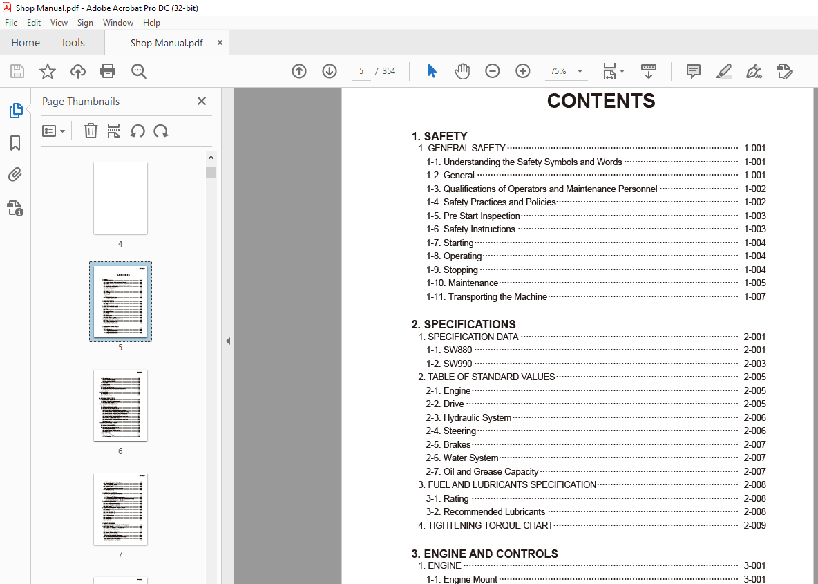
TABLE OF CONTENTS:
Sakai Asphalt Roller SW880 SW990 Service Manual – PDF DOWNLOAD
1. SAFETY
1. GENERAL SAFETY 1-001
1-1. Understanding the Safety Symbols and Words 1-001
1-2. General 1-001
1-3. Qualifications of Operators and Maintenance Personnel 1-002
1-4. Safety Practices and Policies 1-002
1-5. Pre Start Inspection 1-003
1-6. Safety Instructions 1-003
1-7. Starting 1-004
1-8. Operating 1-004
1-9. Stopping 1-004
1-10. Maintenance 1-005
1-11. Transporting the Machine 1-007
2. SPECIFICATIONS
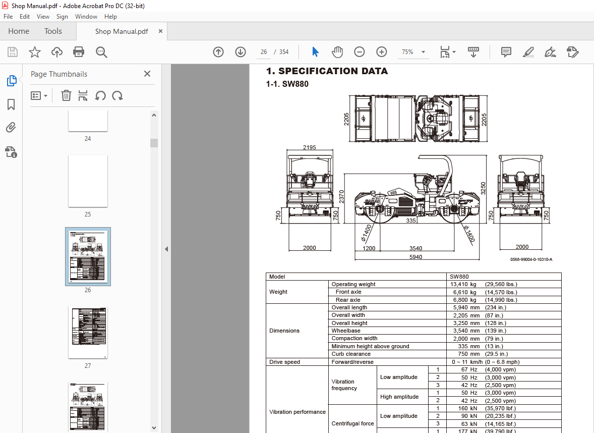
1. SPECIFICATION DATA 2-001
1-1. SW880 2-001
1-2. SW990 2-003
2. TABLE OF STANDARD VALUES 2-005
2-1. Engine 2-005
2-2. Drive 2-005
2-3. Hydraulic System 2-006
2-4. Steering 2-006
2-5. Brakes 2-007
2-6. Water System 2-007
2-7. Oil and Grease Capacity 2-007
3. FUEL AND LUBRICANTS SPECIFICATION 2-008
3-1. Rating 2-008
3-2. Recommended Lubricants 2-008
4. TIGHTENING TORQUE CHART 2-009
3. ENGINE AND CONTROLS
1. ENGINE 3-001
1-1. Engine Mount 3-001
1-1-1. Engine mount (SW880) 3-001
1-1-2. Engine mount (SW990) 3-002
SW880/990○0
1-2. Engine Exterior 3-003
1-2-1. Engine exterior (SW880) 3-003
1-2-2. Engine exterior (SW990) 3-004
1-3. Fuel System 3-005
1-4. Cooling System 3-006
2. CONTROL SYSTEM 3-007
2-1. Forward-reverse Control 3-007
2-2. Adjustment of Forward-reverse Lever Potentiometer 3-008
2-2-1. Adjustment 3-008
3. PUMP MOUNT 3-009
3-1. Pump Mount 3-009
3-2. Installation of Pump 3-010
4. HYDRAULIC SYSTEMS
1. SYSTEM CIRCUIT DIAGRAM 4-001
1-1. Graphic Symbols for Hydraulic Circuits 4-001
1-2. Hydraulic Circuit Diagram 4-003
2. PROPULSION HYDRAULIC SYSTEM 4-004
2-1. Propulsion Hydraulic Piping (1) 4-004
2-2. Propulsion Hydraulic Piping (2) 4-005
2-3. Hydraulic Component Specifications 4-006
2-3-1. Hydraulic pump assembly (propulsion + vibrator) 4-006
2-3-2. Internal structure of hydraulic pump (propulsion pump) 4-008
2-3-3. Internal structure of hydraulic pump (vibrator pump) 4-012
2-3-4. Propulsion hydraulic motor (front) 4-016
2-3-5. Internal structure of propulsion hydraulic motor (front) 4-017
2-3-6. Propulsion hydraulic motor (rear) 4-018
2-3-7. Internal structure of propulsion hydraulic motor (rear) 4-019
2-3-8. Valve block 4-020
3. VIBRATOR HYDRAULIC SYSTEM 4-021
3-1. Vibrator Hydraulic Piping (1) 4-021
3-2. Vibrator Hydraulic Piping (2) 4-022
3-3. Hydraulic Component Specifications 4-023
3-3-1. Vibrator hydraulic motor 4-023
3-3-2. Internal structure of vibrator motor 4-024
3-3-3. Valve block 4-025
4. STEERING SYSTEM 4-027
4-1. Steering Hydraulic Piping 4-027
4-1-1. Steering pump 4-028
SW880/990○0
4-1-2. Internal structure of steering pump 4-029
4-2. Steering Wheel 4-030
4-2-1. Steering valve (orbitrol) 4-031
4-3. Steering Cylinder 4-032
4-3-1. Internal structure of steering cylinder 4-033
4-4. Frame (Center Pin) 4-034
5. ELECTRICAL SYSTEM
1. GENERAL SYSTEM CIRCUIT DIAGRAM 5-001
1-1. Electrical Wiring Diagram 5-001
1-1-1. Engine-related electrical wiring diagram 5-002
1-1-2. Vehicle-related electrical wiring diagram (vehicle control unit) 5-003
1-1-3. Vehicle-related electrical wiring diagram 5-004
2. ELECTRICAL COMPONENTS 5-005
2-1. Electrical Component Layout (1) 5-005
2-2. Electrical Component Layout (2) 5-006
2-3. Battery Layout 5-008
3. ELECTRICAL COMPONENT SPECIFICATIONS 5-009
3-1. Fuse Box 5-009
3-2. Vehicle Control (V/C) 5-010
3-3. Control Box (EMR 3) 5-011
3-4. Resistor 5-012
3-5. Combination Meter 5-013
3-6. Exact Meter 5-014
3-7. Potentiometer 5-015
3-8. Lever Switch 5-016
6. VIBRATORY DRUM
1. PRECAUTIONS FOR DISASSEMBLY AND REASSEMBLY 6-001
2. VIBRATORY DRUM 6-003
2-1. Removal and Installation of Vibratory Drum 6-003
2-1-1. Removal of vibratory drum 6-003
2-1-2. Installation of vibratory drum 6-009
2-2. Vibratory Drum Assembly 6-010
2-2-1. Vibratory drum assembly 6-010
2-2-2. Vibratory drum exploded diagram 6-011
2-3. Disassembly and Reassembly of Vibratory Drum 6-012
2-3-1. Disassembly of vibratory drum 6-012
2-3-2. Reassembly of vibratory drum 6-026
7. BRAKES
1. BRAKE SYSTEM 7-001
1-1. Brake Pedal 7-001
1-2. Brake Circuit Configuration 7-002
8. OPERATOR STATION
1. FLOORBOARD 8-001
1-1. Operator Station 8-001
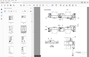
1-2. Structure of Operator Station 8-002
1-3. Adjustment of Swivel Lock Release Pedal 8-003
9. WATER SPRAY SYSTEM
1. WATER SPRAY SYSTEM 9-001
1-1. Water Spray System 9-001
1-2. Water Spray Pump 9-002
10. INSPECTION AND ADJUSTMENT
1. INSPECTION AND ADJUSTMENT 10-001
1-1. Inspection and Adjustment 10-001
1-1-1. Safety precautions for inspection and adjustment 10-001
1-1-2. Preparation for inspection and adjustment 10-002
1-1-3. Precautions for inspection and adjustment 10-002
1-1-4. Warm-up 10-002
2. MEASUREMENT AND ADJUSTMENT OF PROPULSION CIRCUIT
PRESSURE 10-003
2-1. Measurement 10-003
2-2. Adjustment 10-004
2-2-1. If the pressures on both the forward and reverse sides deviate
from the maximum circuit pressure range by the same value 10-004
2-2-2. If the pressure on either the forward or reverse side deviates
from the maximum circuit pressure range 10-005
3. MEASUREMENT AND ADJUSTMENT OF PROPULSION CHARGE
CIRCUIT PRESSURE 10-006
3-1. Measurement 10-006
3-2. Adjustment 10-007
4. MEASUREMENT OF PROPULSION SERVO CIRCUIT PRESSURE 10-008
4-1. Measurement 10-008
5. MEASUREMENT OF PARKING BRAKE RELEASE PRESSURE 10-009
5-1. Measurement 10-009
SW880/990○0
6. MEASUREMENT AND INSPECTION OF VIBRATOR CIRCUIT PRESSURE 10-010
6-1. Measurement 10-010
6-2. Inspection 10-011
6-2-1. Inspection of the high-pressure relief valves installed in the
vibrator pump 10-011
6-2-2. Inspection of the high-pressure relief valves (port relief valves)
installed in the valve blocks in the vibrator circuit 10-012
7. MEASUREMENT AND INSPECTION OF VIBRATION CHARGE
CIRCUIT PRESSURE 10-013
7-1. Measurement 10-013
7-2. Inspection 10-014
8. MEASUREMENT AND INSPECTION OF STEERING CIRCUIT PRESSURE 10-015
8-1. Measurement 10-015
8-2. Inspection 10-016
11. TROUBLESHOOTING
1. TROUBLESHOOTING 11-001
1-1. Safety Precautions for Troubleshooting 11-001
1-2. Important Information for Troubleshooting 11-002
1-3. Before Starting 11-002
1-4. Wire Color Code and Number 11-002
2. ELECTRICAL SYSTEM TROUBLESHOOTING 11-003
2-1. When Performing Electrical System Fault Diagnosis 11-003
2-1-1. Safety rules and precautions to take during electric circuit fault
diagnosis 11-003
2-1-2. Inspection procedures using a tester 11-004
2-1-3. Inspection of electrical system 11-008
2-2. Blink Codes 11-010
2-2-1. Description of blink codes 11-010
2-2-2. Blink code list 11-011
2-3. Error Codes 11-015
2-3-1. Description of error codes 11-015
2-3-2. Error code list 11-015
2-4. Engine 11-017
2-4-1. Engine will not start (1/8) 11-017
2-4-1. Engine will not start (2/8) 11-019
2-4-1. Engine will not start (3/8) 11-021
2-4-1. Engine will not start (4/8) 11-023
2-4-1. Engine will not start (5/8) 11-025
2-4-1. Engine will not start (6/8) 11-027
2-4-1. Engine will not start (7/8) 11-029
2-4-1. Engine will not start (8/8) 11-031
2-4-2. Insufficient output of engine or engine malfunction (1/2) 11-033
2-4-2. Insufficient output of engine or engine malfunction (2/2) 11-035
2-4-3. No charging 11-037
2-4-4. Engine speed cannot be switched 11-039
2-4-5. Glow plug is not heated (Engine starting performance is bad) 11-041
2-4-6. Engine check lamp does not illuminate 11-043
2-4-7. CAN communication is abnormal 11-045
2-5. Propulsion 11-047
2-5-1. Vehicle moves neither forward nor backward (1/5) 11-047
2-5-1. Vehicle moves neither forward nor backward (2/5) 11-049
2-5-1. Vehicle moves neither forward nor backward (3/5) 11-051
2-5-1. Vehicle moves neither forward nor backward (4/5) 11-053
2-5-1. Vehicle moves neither forward nor backward (5/5) 11-055
2-5-2. Vehicle moves neither forward nor backward only in
automatic speed mode 11-057
2-5-3. Vehicle speed cannot be changed 11-059
2-5-4. Automatic speed function does not work (1/7) 11-061
2-5-4. Automatic speed function does not work (2/7) 11-063
2-5-4. Automatic speed function does not work (3/7) 11-065
2-5-4. Automatic speed function does not work (4/7) 11-067
2-5-4. Automatic speed function does not work (5/7) 11-069
2-5-4. Automatic speed function does not work (6/7) 11-071
2-5-4. Automatic speed function does not work (7/7) 11-073
2-5-5. Brake cannot be released 11-075
2-5-6. Brake does not operate 11-077
2-5-7. Emergency exit propulsion cannot be performed 11-079
2-6. Vibration 11-081
2-6-1. No vibration occurs (1/2) 11-081
2-6-1. No vibration occurs (2/2) 11-083
2-6-2. Vibration frequency cannot be switched (1/2) 11-085
2-6-2. Vibration frequency cannot be switched (2/2) 11-087
2-6-3. High/low-vibration cannot be switched 11-089
2-6-4. Continuous/automatic-vibration mode cannot be switched 11-091
2-6-5. Front and rear vibratory drums cannot perform one-drum vibration 11-093
2-7. Exact Meter 11-095
2-7-1. Exact meter indicator lamp does not illuminate (during driving) (1/2) 11-095
2-7-1. Exact meter indicator lamp does not illuminate (during driving) (2/2) 11-097
2-7-2. No vehicle speed indication on the display 11-099
2-8. Water Spray 11-101
2-8-1. Continuous water spray cannot be performed (1/4) 11-101
2-8-1. Continuous water spray cannot be performed (2/4) 11-103
2-8-1. Continuous water spray cannot be performed (3/4) 11-105
2-8-1. Continuous water spray cannot be performed (4/4) 11-107
2-8-2. Continuous water spray works, but intermittent water spray
cannot be performed 11-109
2-8-3. Continuous water spray works, but automatic water spray
cannot be performed 11-111
2-9. Lighting 11-113
2-9-1. Headlamps and working lamps do not light 11-113
2-9-2. Illumination of combination meter does not turn on 11-115
2-9-3. Combination meter warning lamp or indicator lamp is abnormal 11-115
2-9-4. Tachometer reading is abnormal (1/2) 11-117
2-9-4. Tachometer reading is abnormal (2/2) 11-119
2-9-5. Hour meter is abnormal 11-119
2-9-6. Temperature gauge is abnormal 11-121
2-9-7. Fuel gauge is abnormal 11-123
2-9-8. Hydraulic oil filter warning lamp remains ON 11-123
2-9-9. Oil pressure warning lamp remains ON 11-125
2-9-10. Charge warning lamp remains ON 11-127
2-9-11. Vibration indicator lamp does not light 11-127
2-9-12. Water spray indicator lamp does not light 11-129
2-9-13. Working lamp indicator lamp does not light 11-131
2-9-14. Parking brake indicator lamp does not light 11-131
2-9-15. Horn does not sound 11-133
2-9-16. Back buzzer does not sound 11-133
3. HYDRAULIC SYSTEM TROUBLESHOOTING 11-134
3-1. When Performing Hydraulic System Troubleshooting 11-134
3-2. Propulsion 11-135
3-2-1. Vehicle moves neither forward nor backward (1/2) 11-135
3-2-1. Vehicle moves neither forward nor backward (2/2) 11-136
3-2-2. Vehicle moves in one direction only (forward or backward) 11-136
3-2-3. Slow vehicle speed or small drive force 11-136
3-2-4. Vehicle does not stop completely with forward/reverse lever in
neutral position 11-137
3-2-5. Propulsion system is overheating 11-137
3-2-6. Abnormal noise from propulsion system 11-137
3-3. Vibrator System 11-138
3-3-1. No vibration 11-138
3-3-2. Only front or rear vibratory drum can vibrate (two-drum vibration
cannot be performed) 11-139
3-3-3. Vibrator frequency is too low 11-139
3-3-4. Amplitude cannot be switched between high and low 11-139
3-3-5. Vibrator does not stop 11-140
3-3-6. Vibrator system is overheating 11-140
3-3-7. Abnormal noise from vibrator system 11-140
3-4. Steering 11-141
3-4-1. Steering wheel is hard to turn 11-141
3-4-2. Steering response is slow 11-141
3-4-3. Steering wheel backlash or play is large 11-142
3-4-4. Steering system is overheating 11-142
3-4-5. Abnormal noise from steering system 11-142
More products