$37
Sakai CR271 Shop Manual 3498-65634-0 – PDF DOWNLOAD
Sakai CR271 Shop Manual 3498-65634-0 – PDF DOWNLOAD
FILE DETAILS:
Sakai CR271 Shop Manual 3498-65634-0 – PDF DOWNLOAD
Language : English
Pages :170
Downloadable : Yes
File Type : PDF
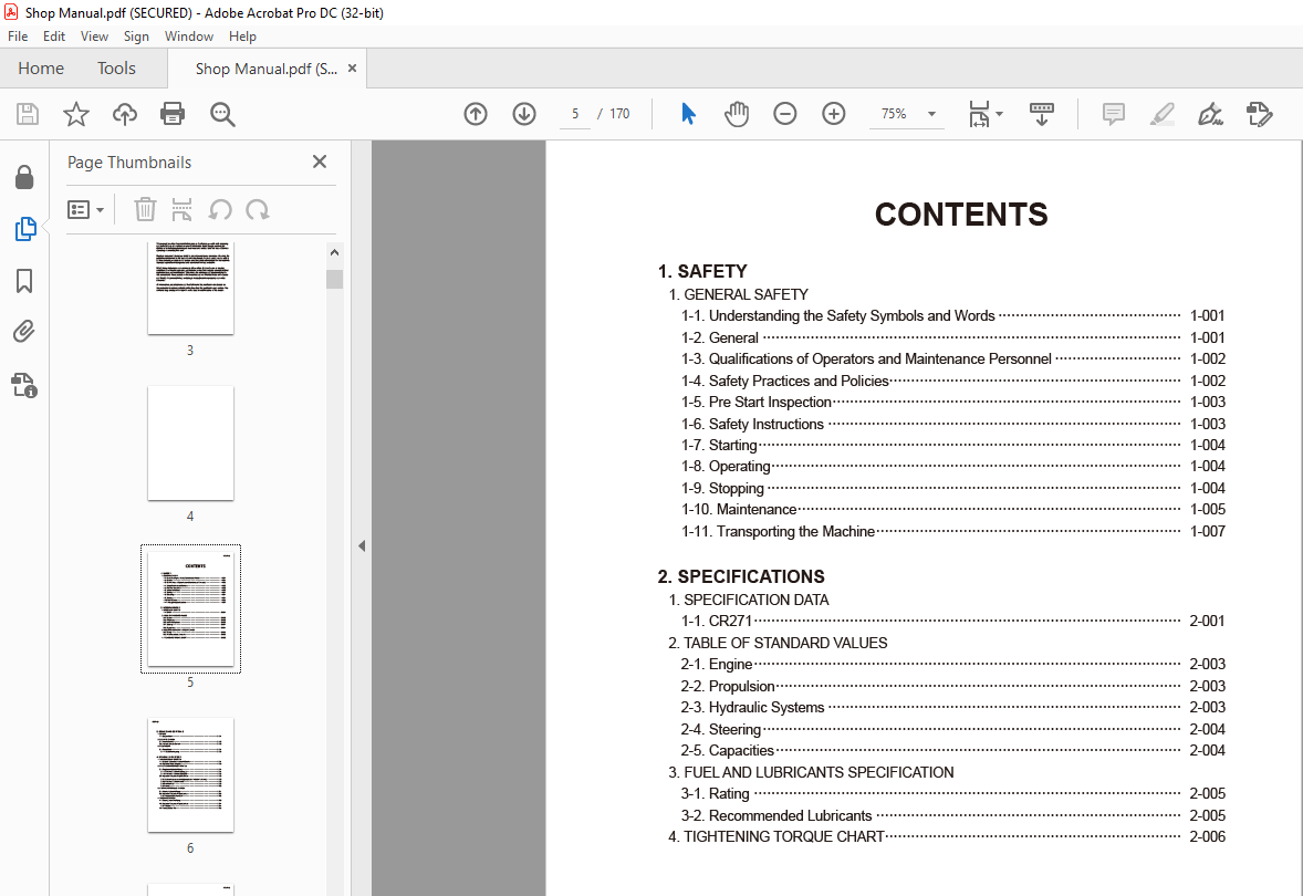
TABLE OF CONTENTS:
Sakai CR271 Shop Manual 3498-65634-0 – PDF DOWNLOAD
1. SAFETY
1. GENERAL SAFETY
1-1. Understanding the Safety Symbols and Words 1-001
1-2. General 1-001
1-3. Qualifications of Operators and Maintenance Personnel 1-002
1-4. Safety Practices and Policies 1-002
1-5. Pre Start Inspection 1-003
1-6. Safety Instructions 1-003
1-7. Starting 1-004
1-8. Operating 1-004
1-9. Stopping 1-004
1-10. Maintenance 1-005
1-11. Transporting the Machine 1-007
2. SPECIFICATIONS
1. SPECIFICATION DATA
1-1. CR271 2-001
2. TABLE OF STANDARD VALUES
2-1. Engine 2-003
2-2. Propulsion 2-003
2-3. Hydraulic Systems 2-003
2-4. Steering 2-004
2-5. Capacities 2-004
3. FUEL AND LUBRICANTS SPECIFICATION
3-1. Rating 2-005
3-2. Recommended Lubricants 2-005
4. TIGHTENING TORQUE CHART 2-006
3. ENGINE AND CONTROLS
1. ENGINE
1-1. Engine Mount 3-001
2. CONTROL SYSTEM
2-1. Throttle Control 3-002
2-2. Forward-reverse Control 3-003
3. PUMP MOUNT
3-1. Pump Mount 3-004
3-1-1. Installation of pump 3-005
4. HYDRAULIC SYSTEMS
1. SYSTEM CIRCUIT DIAGRAM
1-1. Graphic Symbols for Hydraulic Circuits 4-001
1-2. Hydraulic Circuit Diagram 4-003
2. PROPULSION HYDRAULIC SYSTEM
2-1. Propulsion Hydraulic Piping 4-004
2-1-1. Propulsion hydraulic piping (1) 4-004
2-1-2. Propulsion hydraulic piping (2) 4-005
2-2. Hydraulic Component Specifications 4-006
2-2-1. Hydraulic pump assembly (propulsion + vibrator + steering) 4-006
2-2-2. Propulsion hydraulic motor 4-008
2-2-3. Valve block 4-009
2-2-4. Valve 4-010
3. VIBRATOR HYDRAULIC SYSTEM
3-1. Vibrator Hydraulic Piping 4-011
3-2. Hydraulic Component Specification 4-012
3-2-1. Vibrator hydraulic motor 4-012
4. STEERING SYSTEM
4-1. Steering Hydraulic Piping 4-013
4-2. Hydraulic Component Specifications 4-014
4-2-1. Orbitrol 4-014
4-3. Frame (Center Pin) 4-015
CR271 ○0
5. ELECTRICAL SYSTEM
1. Precautions for wor k
1-1. W ire Numbers, Wire Sizes, Wire Colors and Connectors Shown in
Electrical Circuit Diagrams, Wiring Harness Layout and Wiring Harnesses 5-001
2. SYSTEM CIRCUIT DIAGRAM
2-1. Electrical Circuit Diagram 5-003
3. ELECTRICAL COMPONENTS
3-1. Electrical component Layout 5-004
4. WIRING HARNESSES
4-1. Harness (1) 5-005
4-2. Harness (2) 5-007
6. DRUMS
1. PRECAUTIONS FOR DISASSEMBLY AND REASSEMBLY 6-001
2. REMOVAL AND INSTALLATION OF DRUMS
2-1. Removal of Drums 6-003
2-1-1. Front drum 6-003
2-1-2. Rear drum 6-006
2-2. Installation of Drums 6-008
3. DRUM ASSEMBLY
3-1. Front Drum 6-009
3-2. Rear Drum 6-010
4. DISASSEMBLY AND REASSEMBLY OF DRUMS
4-1. Disassembly of Drums 6-011
4-1-1. Front drum 6-011
4-1-2. Rear drum 6-018
4-2. Reassembly of Drums 6-024
4-2-1. Front drum 6-024
4-2-2. Rear drum 6-034
7. PARKING BRAKE
1. PARKING BRAKE
1-1. Brake 7-001
8. WATER SPRAY SYSTEM
1. WATER SPRAY SYSTEM
1-1. Water spray 8-001
9. INSPECTION AND ADJUSTMENT
1. INSPECTION AND ADJUSTMENT
1-1. Safety Precautions for Inspection and Adjustment 9-001
1-2. Preparation for Inspection and Adjustment 9-001
1-3. Precautions for Inspection and Adjustment 9-001
1-4. Warm-up 9-001
1-5. Inspection and Adjustment of Engine Related Items 9-001
2. MEASUREMENT AND INSPECTION OF PROPULSION CIRCUIT PRESSURE
2-1. Measurement 9-002
2-2. Adjustment 9-003
3. MEASUREMENT AND INSPECTION OF PROPULSION CHARGE CIRCUIT
PRESSURE 9-004
3-1. Measurement 9-004
3-2. Adjustment 9-005
4. MEASUREMENT AND ADJUSTMENT OF STEERING CIRCUIT PRESSURE
4-1. Measurement 9-006
4-2. Adjustment 9-007
5. MEASUREMENT OF HYDRAULIC PUMP CASE PRESSURE
5-1. Measurement 9-008
6. MEASUREMENT OF PROPULSION MOTOR CASE PRESSURE
6-1. Measurement 9-009
7. ADJUSTMENT OF THROTTLE LEVER LINKAGE
7-1. Adjustment 9-010
8. ADJUSTMENT OF F-R LEVER LINKAGE
8-1. Adjustment 9-012
10. TROUBLESHOOTING
1. TROUBLESHOOTING
1-1. Safety Precautions for Troubleshooting 10-001
1-2. Important Information for Troubleshooting 10-001
1-3. Before Starting 10-002
1-4. Wire Number and Color Code 10-002
2. ELECTRICAL SYSTEM TROUBLESHOOTING
2-1. When Performing Electrical System Fault Diagnosis 10-003
2-1-1. Precautions to take during electrical circuit fault diagnosis 10-003
2-1-2. Inspection procedures using a tester 10-004
2-1-3. Inspection of electrical system 10-009
2-2. Engine 10-012
CR271 ○0
2-2-1. Engine will not start (Starter motor does not run) 10-012
2-2-2. Engine will not start (But starter motor runs) 10-014
2-2-3. No charging 10-016
2-2-4. Starter motor runs even when F-R lever is not at “N” applied 10-016
2-3. Propulsion 10-018
2-3-1. Hour meter is abnormal 10-018
2-3-2. Horn does not sound 10-018
2-4. Vibration 10-020
2-4-1. No vibration occurs 10-020
3. HYDRAULIC SYSTEM TROUBLESHOOTING
3-1. When Performing Hydraulic System Troubleshooting 10-021
3-2. Propulsion System 10-022
3-2-1. Machine moves neither forward nor backward 10-022
3-2-2. Machine moves in one direction only (forward or backward) 10-023
3-2-3. Slow machine speed or small drive force 10-023
3-2-4. Machine does not stop completely with F-R lever in “N” 10-024
3-2-5. Propulsion system is overheating 10-024
3-2-6. Abnormal noise from propulsion system 10-024
3-3. Steering System 10-025
3-3-1. Steering wheel is hard to turn 10-025
3-3-2. Steering response is slow 10-025
3-3-3. Steering wheel backlash or play is large 10-026
3-3-4. Steering system is overheating 10-026
3-3-5. Abnormal noise from steering system 10-026
IMAGES PREVIEW OF THE MANUAL:
More products