$38
Sakai GW754 Shop Manual 3498-6539b-0 – PDF DOWNLOAD
Sakai GW754 Shop Manual 3498-6539b-0 – PDF DOWNLOAD
FILE DETAILS:
Sakai GW754 Shop Manual 3498-6539b-0 – PDF DOWNLOAD
Language : English
Pages :384
Downloadable : Yes
File Type : PDF
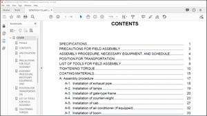
TABLE OF CONTENTS:
Sakai GW754 Shop Manual 3498-6539b-0 – PDF DOWNLO1. SAFETY CONTENTS
General 1-1
1. GENERAL SAFETY 1-2.
. Understanding the Safety Symbols and Words 1-3.
Qualifications of Operators and Maintenance Personnel 1-4.
Safety Practices and Policies. 1-5.
Pre Start Inspection… 1-6.
Safety Instructions 1-7.
Starting. 1-8.
Operating 1-9.
Stopping 1-10.
Maintenance. 1-11.
Transporting the Machine-
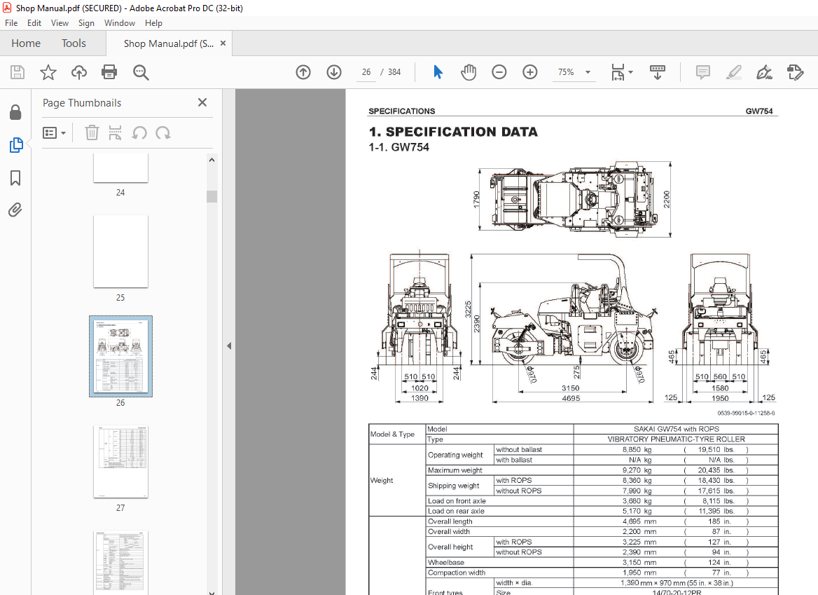
2. SPECIFICATIONS
. SPECIFICATION DATA 1-1. GW754………. 2-001
2. TABLE OF STANDARD VALUES 2-1. Engine 2-004
2-2. Propulsion- 2-004
2-3. Hydraulic System- 2-004
2-4. Steering 2-005 2-5. Brakes-
2-005 2-6. Capacities- 2-005
3. FUEL AND LUBRICANTS SPECIFICATION
3-1. Rating 2-006 3-2. Recommended Lubricants 2-006
4. TIGHTENING TORQUE CHART 2-007
3. ENGINE AND CONTROLS
1. ENGINE 1-1.
Engine Mount 1-2.
Engine Exterior
2. FUEL SYSTEM
3-2. Hydraulic Component Specifications
3-2-1. Vibrator hydraulic pump
3-2-2. Vibrator hydraulic motor (
3-2-3. Vibrator hydraulic motor
Valve block ASSY (amplitude)
3-2-5. Amplitude cylinder
3-2-6. Amplitude cylinder
3-2-7. Vibrator solenoid valve
3-2-8. Flow divider
. Description and Operation of Vibrator System
4-034 4. STEERING SYSTEM
4-1. Steering Hydraulic Piping- 4-035
4-2. Steering Wheel 4-036
4-3. Hydraulic Component Specifications 4-037
4-3-1. Steering charge pump.. 4-037
4-3-2. Orbitrol……. 4-038 4-4. Description and Operation of Steering System.
4-4-1. Description and operation of steering system.
4-4-2. Structure and operation of Orbitrol
5. ELECTRICAL SYSTEM
1. PRECAUTIONS FOR WORK 1-1.
Wire Numbers,
Wire Sizes,
Wire Colors and Connectors Shown in Electrical Circuit Diagram, Wiring Harness Layout and Wiring Harnesses….. 5-001
2. SYSTEM CIRCUIT DIAGRAM
2-1. Electrical Circuit Diagram
3. ELECTRICAL COMPONENTS
3-1. Wiring Harness Layout (1)
3-2. Wiring Harness Layout (2)-
3-3. Wiring Harness Layout (3)
4. WIRING HARNESSES . 4-1. Fuse
Relay Harness.
4-2. Amplitude Cylinder Solenoid Harness
4-3. ECU Harness 5-011
4-4. ACU Harness 5-013
4-5. Dashboard Harness 5-015
4-6. Air Flow Sensor Harness
4-7. Battery Relay Harness
4-8. Member (F) Harness 5-020
4-9. Member (R) Harness-
4-10. Battery Box Connect Harness
4-11. Engine Harness
4-12. Starter Switch Harness
4-13. Head Lamp Harness
4-14. F-R Lever Hamess
4-15. F-R Lever Vibration Switch Hamess
4-16. Amplitude Cylinder Switch Harness
4-17. Amplitude Cylinder Switch Harness
4-18. Amplitude Cylinder Switch Harness
4-19. Water Spray Pump Hamess 5-030 5-031
4-20. Cord…. 5-032
4-21. Ground Cord 1 5-033
4-22. Ground Cord 2. 5-034
4-23. Ground Cord 3. 5-035
5. ELECTRICAL COMPONENT SPECIFICATIONS
5-1. Fuse Box 1
5-2. Fuse Box 2
5-3. Combination Meter-
6. WHEEL AND VIBRATOR SYSTEM
1. PRECAUTIONS FOR DISASSEMBLY AND REASSEMBLY.
6-001 2. FRONT WHEEL
2-1. Removal and Installation of Front Wheel ASSY
6-003 2-1-1. Removal of front wheel ASSY….
6-003 2-1-2. Installation of front wheel ASSY
6-006 2-2. Front Wheel ASSY 6-007 2-3. Disassembly and Reassembly of Front Wheel
6-008 2-3-1. Disassembly of front wheel… 6-008 2-3-2.
Reassembly of front wheel
6-017 3. REAR WHEEL
3-1. Removal and Installation of Rear Wheel ASSY
6-037 3-1-1. Removal of rear wheel ASSY…….. 6-037
3-1-2. Installation of rear wheel ASSY 6-042 3-2.
Rear Wheel ASSY…………. 6-043
3-3. Disassembly and Reassembly of Rear Wheel
3-3-1. Disassembly of rear wheel
3-3-2. Reassembly of rear wheel 6-055
IMAGES PREVIEW OF THE MANUAL:

More products