$32.95
Sakai Soil Roller SV400 Series Shop Manual – PDF DOWNLOAD
Sakai Soil Roller SV400 Series Shop Manual – PDF DOWNLOAD
The Sakai Soil Roller SV400 Series Shop Manual PDF DOWNLOAD is a detailed reference for servicing and repairing SV400D, SV400T, and SV400TF models. It offers comprehensive guidance for maintenance, troubleshooting, and repair procedures, ensuring optimal performance.
FILE DETAILS:
Sakai Soil Roller SV400 Series Shop Manual – PDF DOWNLOAD
Language : English
Pages : 149
Downloadable : Yes
File Type : PDF
DESCRIPTION
Sakai Soil Roller SV400 Series Shop Manual – PDF DOWNLOAD
About the Manual
This manual is divided into Sections. The sections and brief overviews are listed below:
• Introduction – Supplies directions on how to use the manual, general safety instructions. Panel
symbols used on the compactor. Acronyms and Abbreviations pages give noun names for
common acronyms and abbreviations.
• Identification – Identifies the components on the compactor and breaks them down into exploded
views.
• Operation – Describes components and operating procedures for the compactor.
• Maintenance – Supplies maintenance intervals for the compactor.
• Troubleshooting – The troubleshooting section is divided into procedures that are symptom
driven. The most common problems are addressed first.
• Compactor Repair – Procedures to replace individual components.
• Schematics – Hydraulic and electrical schematics are supplied.
• Service Literature – Lists service literature that can be acquired.
• Specifications – Supplies specifications for the compactor. Conversion charts are also supplied in
this section.
The instructions in this manual must be followed to operate, maintain, troubleshoot and repair the
compactor.
IMAGES PREVIEW OF THE MANUAL:
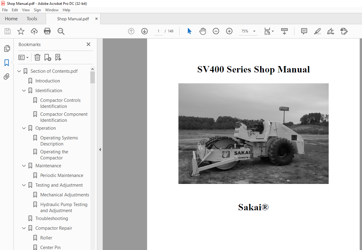
TABLE OF CONTENTS:
Sakai Soil Roller SV400 Series Shop Manual – PDF DOWNLOAD
Section Page
Introduction
About the Manual 1-1
How to Use the Manual 1-2
Panel Symbols1-3
General Safety Instructions1-5
Acronyms and Abbreviations 1-15
Identification
Compactor Controls Identification
Left View 2-2
Right View2-3
Operators Station 2-4
Compactor Component Identification
Rear Drive Hydraulic Hoses 2-5
Front Drive Hydraulic Hoses 2-6
Steering Hoses 2-7
Hydraulic Brake Hose Network2-8
Vibration Hose Network 2-9
Brake Linkage2-10
Compactor Left Side View 2-11
Compactor Top View2-12
Forward/Reverse Cable2-13
Cooling System2-14
Engine Components 2-15
Exhaust System2-16
Fuel Lines 2-17
Intake Air System 2-18
Battery Cable Routing2-19
Operators Station 2-20
Electric Component Locations2-21
Brake Cylinder 2-22
Brake Pedal 2-23
Center Pin 2-24
Roller (D)2-25
Roller (T) 2-26
Roller (TF) 2-27
Differential2-28
Drive Wheels 2-29
Final Drive 2-30
Front Drive Propulsion Motor 2-31
Hydraulic Pump Assembly 2-32
Pump to Engine Coupling2-33
Orbitrol2-34
Operator’s Seat 2-35
Parking Brake 2-36
Rear Drive Propulsion Motor2-37
Reduction Gear 2-38
Steering Cylinder 2-39
Vibration Motor 2-40
Operation
Operating Systems Description
Diesel Engine3-1
Hydraulic Drive System3-2
Hydraulic Drive Circuit 3-3
Hydraulic Vibratory System 3-5
Hydraulic Vibratory Circuit 3-6
Hydraulic Steering System3-7
Hydraulic Steering Circuit 3-8
Brake System 3-9
Combination Meter 3-11
Monitor Display3-12
Tachometer 3-13
Temperature Gauge3-13
Fuel Gauge3-13
Engine Lamps 3-13
Starter Switch3-13
Parking Brake Switch 3-14
Horn Button 3-14
Vibrator Amplitude Switch3-14
Vibrator Selector Switch3-15
Forward/Reverse Lever Vibration ON/OFF Switch 3-15
Compactor Speed Change Switch3-15
Forward/Reverse Lever3-16
Unloader Valve 3-16
Throttle Lever 3-17
Fuse Box 3-17
Operating the Compactor
Release Brakes for Towing3-18
Before Starting Inspection 3-19
Starting the Engine3-20
ii i
Traveling3-22
Stopping and Parking3-23
Stopping the Engine3-24
Vibratory Operation 3-24
Loading Using a Winch Equipped Trailer 3-26
Self Propelled Loading 3-28
Working With the Compactor3-29
Maintenance
Periodic Maintenance
Compactor Maintenance Schedule4-2
Compactor Component Replacement Schedule4-3
Prior to Starting the Compactor 4-4
Lifting Compactor with Hoist 4-5
Maintenance Procedures Every 10 Hours or Daily4-5
Maintenance Procedures Every 50 Hours4-6
Maintenance Procedures Every 250 Hours4-7
Maintenance Procedures Every 500 Hours4-10
Maintenance Procedures Every 1,000 Hours4-13
As Required 4-15
Booster Cable Connection 4-17
Long Term Storage 4-19
Testing and Adjustment
Mechanical Adjustments
Seat Adjustment 5-1
Scraper Adjustment5-1
Hydraulic Pump Testing and Adjustment
Measure Hydraulic Pressure Main Propulsion Circuit5-2
Adjust Hydraulic Pressure Main Propulsion Circuit5-3
Measure Propulsion Charge Pressure 5-4
Adjust Propulsion Charge Pressure 5-5
Measure Propulsion Motor Speed Shift Valve 5-6
Measure Vibrator Circuit Pressure5-7
Adjust Vibrator Circuit Pressure5-8
Measure Vibrator Charge Pressure 5-9
Adjust Vibrator Charge Pressure 5-10
Measure Steering Circuit Pressure5-10
Adjust Forward/Reverse Cable 5-11
Throttle Linkage Adjustment 5-12
Parking Bake Adjustment 5-13
Troubleshooting
Troubleshooting Guidelines6-1
Wiring Diagram Color Codes 6-2
Engine Warning Lamp is Illuminated 6-4
Engine Stop Lamp is Illuminated6-8
Wait to Start Lamp is Illuminated6-12
Vibration Lamp Does Not Illuminate When Vibration Engaged6-16
Parking Brake Lamp Does Not Illuminate When Parking Brake Engaged 6-25
Engine Oil Pressure Lamp Illuminated 6-29
Hydraulic Oil Filter Lamp Illuminated 6-34
Tachometer Does Not Indicate Engine Speed 6-39
Hour Meter Does Not Work 6-49
Coolant Temperature Gauge Does Not Work6-55
Fuel Gauge Does Not Work6-60
Backup Alarm Does Not Work6-64
Horn Does Not Work6-71
Compactor Steering Malfunction6-80
Vibration Does Not Work6-85
Low Amplitude Vibration Setting Does Not Work 6-98
High Amplitude Vibration Setting Does Not Work6-104
Can Not Turn Vibration From Forward/Reverse Lever6-110
Compactor Will Not Start 6-116
Engine Will Not Idle Correctly6-134
Engine Will Not Reach MID Speed6-139
Engine Will Not Reach Full Speed 6-144
Compactor Will Not Move Forward and/or Reverse or Does Not Drive Correctly 6-151
Parking Brake Does Not Work 6-158
Compactor Will Not Change Speeds 6-166
Compactor Repair
Roller
Remove 7-1
Disassemble (Vibratory Motor Side) 7-4
Disassemble (Drive Motor Side)7-9
Clean and Inspect for Reuse 7-12
Assemble (Drive Motor) 7-16
Assemble (Vibratory Motor)7-20
Install 7-27
Center Pin
Remove 7-29
Disassemble 7-30
Clean 7-32
Assemble7-32
v i
Install 7-36
Operators Station
Remove 7-38
Install 7-40
Manual Vibration Control Switch
Remove 7-42
Install 7-43
Vibratory Control Panel Switches
Remove 7-43
Install 7-44
Combination Meter
Remove 7-45
Install 7-46
Parking Brake Button
Remove 7-48
Install 7-48
Engine Status Lamps
Remove 7-49
Install 7-50
Engine Start Switch
Remove 7-51
Install 7-51
Directional Control Lever Cable
Remove 7-54
Install 7-55
Directional Control Lever Micro-Switches
Remove 7-56
Disassemble 757
Assemble7-57
Install 7-58
Foot Brake Switch
Remove 7-58
Disassemble 7-59
Assemble7-59
Install 7-59
Speed Sensor (Combination Meter Tachometer)
Remove 7-60
Install 7-60
Coolant Temperature Sensor (Combination Meter Temperature Gauge)
Remove 7-61
Install 7-62
Fuel Level Sensor (Combination Meter Fuel Level Gauge)
Install 7-62
Remove 7-63
Battery Relay
Remove 7-63
Install 7-64
Operator’s Station Relay and Diodes
Remove 7-65
Install 7-65
Horn
Remove 7-66
Install 7-66
Hydraulic Oil Filer Switch
Remove 7-66
Install 7-66
vi ii
Tachometer Control Box
Remove 7-67
Install 7-67
Radiator and Cooling System
Remove 7-67
Install 7-69
Hydraulic Tank
Remove 7-71
Install 7-72
Engine and Pump Assembly
Remove 7-73
Disassemble 7-78
Assemble7-80
Install 7-83
Rear End
Remove 7-90
Install 7-91
Back Up Alarm
Remove 7-92
Install 7-93
Starter Relay
Remove 7-93
Install 7-94
Engine Speed Change Switch
Remove 7-94
Install 7-95
Forward/Reverse Lever Vibration Switch
Remove 7-96
Install 7-97
Fuses 65 Amp and Above
Remove 7-98
Install 7-98
Parking Brake Valve
Remove 7-98
Install 7-99
Vibration Amplitude Solenoid
Remove 7-99
Install 7-100
Compactor Speed Solenoid
Remove 7-100
Install 7-101
Orbitrol Steering Valve
Remove 7-101
Install 7-102
Schematics
Electrical 8-1
Hydraulic 8-2
Service Literature
Additional Service Literature9-1
Specifications
Compactor General Specifications10-1
Hydraulic Pump Pressures 10-5
Overall Coolant Levels 10-5
Battery Electrolyte Reading 10-5
Compactor Capacity10-5
Fuel Oil and Grease Rating10-6
Recommended Lubricants10-6
Rear Drive Specifications 10-6
Compactor Bolt Torques10-7
Hydraulic Motor Specifications 10-8
Metric to US Torque 10-9
Fraction to Decimal to Millimeter Conversions10-10
Metric Drill and Tap Chart10-12
Weights and Measures Conversion Factors 10-16
More products