$33.95
Sakai Soil Roller SV510-II Shop Manual PDF
Sakai Soil Roller SV510-II Shop Manual – PDF DOWNLOAD
The Sakai SV510-II Shop Manual is essential for maintenance. Covering SV510-II soil rollers, it ensures efficient servicing and repairs.
FILE DETAILS:
Sakai Soil Roller SV510-II Shop Manual – PDF DOWNLOAD
Language : English
Pages : 220
Downloadable : Yes
File Type : PDF
DESCRIPTION
Sakai Soil Roller SV510-II Shop Manual – PDF DOWNLOAD
Introduction
- This manual provides important information to familiarize you with safe operating and maintenance procedures for your SAKAI roller. Even though you may be familiar with similar equipment you must read and understand this manual before operating or servicing this unit.
- Safety is everyone’s business and it is one of your primary concerns. Knowing the guidelines presented in this manual will help provide for your safety, for the safety of those around you and for the proper operation and maintenance of the machine. Improper operation is dangerous and can result in injury or death.
- Sakai Heavy Industries cannot foresee all possible circumstances or varying conditions to which the operator, serviceman or machine may be exposed to that might lead to a potential hazard. Therefore, the warnings and cautions listed in this manual and those placed on the machine are not intended to be all inclusive and liability for personal injury or damage to equipment or property cannot be assumed.
IMAGES PREVIEW OF THE MANUAL:
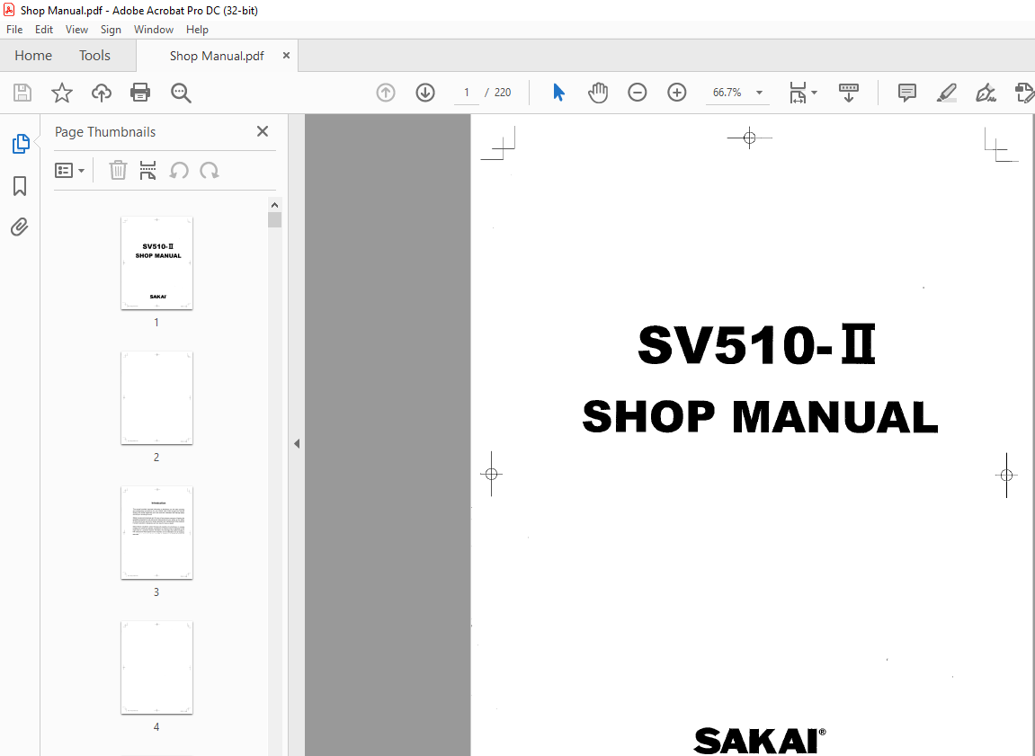
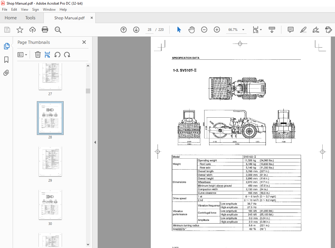
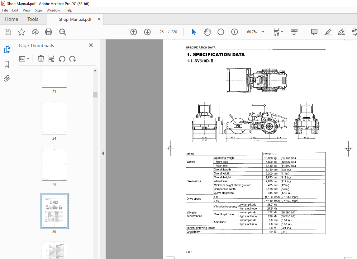
TABLE OF CONTENTS:
Sakai Soil Roller SV510-II Shop Manual – PDF DOWNLOAD
1 SAFETY
1 GENERAL SAFETY 1-001
1-1 Understanding the Safety Symbols and Signal Words 1-001
1-2 General 1-001
1-3 Qualifications of Operators and Maintenance Personnel 1-002
1-4 Safety Practices and Policies 1-002
1-5 Pre Start Inspection 1-003
1-6 Safety Instructions 1-003
1-7 Starting 1-004
1-8 Operating 1-004
1-9 Stopping 1-004
1-10 Maintenance 1-005
1-11 Transporting the Machine 1-007
2 SPECIFICATIONS
1 SPECIFICATION DATA 2-001
1-1 SV51 OD-II 2-001
1-2 SV510T-II 2-003
1-3 SV51 OTB- II 2-005
1-4 SV51 0TF- II 2-007
1-5 SV51 0TFB-II 2-009
2 TABLE OF STANDARD VALUES 2-011
2-1 Engine 2-011
2-2 Drive device 2-011
2-3 Hydraulic devices 2-012
2-4 Steering devices 2-012
2-5 Brakes 2-013
2-6 Oil and grease capacity 2-013
3 FUEL AND LUBRICANTS SPECIFICATION 2-014
3-1 Rating 2-014
3-2 Recommended lubricants 2-014
4 TIGHTENING TORQUE CHART 2-015
3 ENGINE AND CONTROLS
1 ENGINE 3-001
1-1 Engine mount 3-001
2008/06/11 10,30,,rF
+
2 CONTROL SYSTEM 3-002
2-1 Throttle control 3-002
2-2 Forward-reverse control 3-003
3 PUMP MOUNT 3-004
3-1 Pump mount (SV51 0D/T/TF-II) 3-004
3-2 Pump attachment (SV51 0D/T/TF- II) 3-005
3-3 Pump mount (SV51 0TB/TFB- II) 3-007
3-4 Pump attachment (SV51 0TB/TBF-II) 3-008
4 HYDRAULIC SYSTEMS
1 SYSTEM CIRCUIT DIAGRAM 4-001
1-1 Graphic symbols for hydraulic 4-001
1-2 Hydraulic circuit diagram (SV51 0D/T/TF- II) 4-003
1-3 Hydraulic circuit diagram (SV510TB/TFB-II) 4-004
2 PROPULSION HYDRAULIC SYSTEM 4-005
2-1 Propulsion hydraulic piping (1) (front) 4-005
2-2 Propulsion hydraulic piping (2) (rear) 4-006
2-3 Hydraulic equipment specifications 4-007
2-3-1 Propulsion pump
(propulsion, vibrator, steering/charge) (SV51 0D/T/TF- II) 4-007
2-3-2 Propulsion pump
(propulsion, vibrator, steering/charge) (SV51 0TB/TFB-II) 4-008
2-3-3 Propulsion hydraulic motor (front) 4-009
2-3-4 Internal structure of propulsion hydraulic motor (front) , 4-010
2-3-5 Propulsion hydraulic motor (rear) 4-011
2-3-6 Differential lock valve 4-012
2-3-7 Manifold (for differential lock valve) 4-013
2-3-8 Flow dividing valve 4-014
2-3-9 Internal siructure of flow dividing valve 4-015
3 VIBRATOR HYDRAULIC SYSTEM 4-016
3-1 Vibrator hydraulic piping 4-016
3-2 Hydraulic equipment specifications , , 4-017
3-2-1 Vibrator hydraulic rnotor 4-017
4 STEERING SYSTEM 4-018
4-1 Steering hydraulic piping (SV51 0D/T/TF-II) 4-018
4-2 Steering hydraulic piping (SV51 0TB/TFB-II) 4-019
4-3 Frame (center pin) 4-020
4-4 Steering wheel 4-021
4-4-1 Steering valve (Orbitrol) 4-022
~ 00_’11~,rx_E_SV510-1U,;dd 006 2008/06/11 l039’4rF
+
4-5 Steering cylinder 4-023
4-5-1 Internal structure of steering cylinder 4-024
5 BLADE 4-025
5-1 Blade hydraulic piping (SV510TB/TFB-Il) 4-025
5-2 Hydraulic equipment specifications 4-026
5-2-1 Control valve 4-026
5-2-2 Internal structure of cylinder 4-027
5-2-3 Flow dividing valve 4-028
5 ELECTRICAL SYSTEM
1 GENERAL SYSTEM CIRCUIT DIAGRAM 5-001
1-1 Electrical wiring diagram 5-001
2 ELECTRICAL COMPONENTS 5-002
2-1 Electrical component layout ( 1) 5-002
2-2 Electrical component layout (2) 5-003
2-3 Battery layout 5-004
3 ELECTRICAL COMPONENT SPECIFICATIONS 5-005
3-1 Fuse box 5-005
3-2 Engine stop system 5-006
3-2-1 Engine stopper functions and operation 5-007
3-3 Diode unit 5-009
6 VIBRATORY DRUM REAR AXLE
1 PRECAUTIONS FOR DISASSEMBLY AND REASSEMBLY 6-001
2 VIBRATORY DRUM 6-003
2-1 Removal and installation of vibratory drum 6-003
2-1-1 Removal of vibratory drum 6-003
2-1-2 Installation of vibratory drum 6-006
2-2 Vibratory drum assembly 6-007
2-3 Disassembly and reassembly of vibratory drum 6-008
2-3-1 Disassembly of vibratory drurn 6-008
2-3-2 Reassembly of vibratory drurn 6-014
3 AXLE 6-022
3-1 Rear axle 6-022
3-2 Rear axle lubrication 6-023
3-3 Rear axle structure 6-024
3-3-1 Gearbox 6-024
3-3-2 Center housing 6-025
3-3-3 Differential 6-026
+
~ oo_«l~ei:k_E_SVSIO-ILh,cd 007 2008/00/1 I I03′,4rF
3-3-4 Hub reduction gear 6-027
3-3-5 Brake 6-028
7 BRAKES
1 BRAKE SYSTEM 7-001
1-1 Brake pedal 7-001
1-2 Brake circuit configuration 7-002
1-3 Brake piping 7-003
1-4 Brake solenoid valve 7-004
2 BRAKE STRUCTURE 7-005
3 BRAKE ADJUSTMENT 7-006
3-1 Brake clearance adjustment 7-006
3-2 Manually releasing the brake 7-007
8 INSPECTION AND ADJUSTMENT
1 INSPECTION AND ADJUSTMENT 8-001
1-1 Inspection and Adjustment 8-001
1-1-1 Safety precautions for inspection and adjustment 8-001
1-1-2 Preparation for inspection and adjustment 8-002
1-1-3 Precautions for inspection and adjustment 8-002
1-1-4 Warm-up 8-002
2 MEASUREMENT AND ADJUSTMENT OF PROPULSION
CIRCUIT PRESSURE 8-003
2-1 Measurement 8-003
2-2 Adjustment 8-004
3 MEASUREMENT AND ADJUSTMENT OF PROPULSION CHARGE
CIRCUIT PRESSURE 8-005
3-1 Measurement 8-005
3-2 Adjustment 8-006
4 MEASUREMENT OF VEHICLE HIGH/LOW-SPEED CHANGE
CIRCUIT PRESSURE 8-007
4-1 Measurement 8-007
5 MEASUREMENT OF PARKING BRAKE RELEASE PRESSURE 8-008
5-1 Measurement 8-008
6 MEASUREMENT AND INSPECTION OF VIBRATOR CIRCUIT PRESSURE 8-009
6-1 Measurement 8-009
6-2 Inspection 8-01 o
7 MEASUREMENT AND INSPECTION OF VIBRATION CHARGE
CIRCUIT PRESSURE 8-011
~ oo_,,l~l1>LE_SV510-Hiodd 008 2008106/11 10,39-4rF
7-1 Measurement 8-011
7-2 Inspection 8-012
8 MEASUREMENT AND INSPECTION OF STEERING CIRCUIT PRESSURE 8-013
8-1 Measurement 8-01 3
8-2 Inspection 8-014
9 ADJUSTMENT OF THROTTLE LEVER LINKAGE 8-015
9-1 Adjustment 8-015
10 ADJUSTMENT OF FORWARD-REVERSE LEVER LINKAGE 8-016
10-1 Adjustment 8-016
9 TROUBLESHOOTING
1 TROUBLESHOOTING 9-001
1-1 Safety precautions for troubleshooting 9-001
1-2 Important information for troubleshooting 9-002
1-3 Before starting a troubleshooting session 9-002
1-4 Wire color code 9-002
2 FAULT DIAGNOSIS OF ELECTRICAL SYSTEM 9-003
2-1 When performing electrical system fault diagnosis 9-003
2-1-1 Precautions to take during electric circuit fault diagnosis 9-003
2-1-2 Inspection of electrical system 9-003
2-2 Engine 9-007
2-2-1 Engine Will Not Start (Starter Motor Does Not Run) 9-007
2-2-2 Engine Will Not Start (But Starter Motor Runs) 9-009
2-2-3 Engine Does Not Stop Running 9-009
2-2-4 No Charging 9-011
2-2-5 Glow Plug Is Not Heated (Engine Starting Performance Is Bad) 9-011
2-2-6 Starter Motor Runs Even Without Forward/Reverse Lever In Neutral 9-011
2-3 Propulsion 9-013
2-3-1 Vehicle Moves Neither Forward Nor Backward 9-013
2-3-2 Differential Lock Does Not Function 9-013
2-3-3 Dragging Of The Roll Occurs During Driving
When The Differential Is Locked 9-013
2-3-4 Vehicle Speed (Gear) Does Not Change 9-015
2-3-5 Brake Does Not Release 9-017
2-3-6 Brake Does Not Operate 9-017
2-4 Vibrator 9-019
2-4-1 No Vibration Occurs 9-019
2-4-2 Amplitude Does Not Change (Remains Either Low or High) 9-01 9
2-4-3 Vibrator Control Is Continnously Engaged Or
2008/06/1] ]0394rF
Does Not Change When The Forward/Reverse Lever Is Operated 9-021
2-5 Lighting and accessories 9-023
2-5-1 Combination Meter Monitor Lamps Do Not Light 9-023
2-5-2 Tachometer Reading Is Abnormal 9-023
2-5-3 Hour Meter Is Abnormal 9-025
2-5-4 Temperature Gauge Is Abnormal 9-025
2-5-5 Fuel Gauge Is Abnormal 9-025
2-5-6 Hydraulic Oil Filter Warning Lamp Remains ON 9-027
2-5-7 Oil Pressure Warning Lamp Remains ON 9-027
2-5-8 Vibrator Operation Indicator Lamp Does Not Turn ON 9-027
2-5-9 Parking Brake Indicator Lamp Does Not Light 9-029
2-5-10 Horn Does Not Sound 9-029
2-5-11 Backup Buzzer Does Not Beep 9-031
3 HYDRAULIC SYSTEM TROUBLESHOOTING 9-032
3-1 When performing hydraulic system troubleshooting 9-032
3-2 Propulsion 9-033
3-2-1 Vehicle Moves Neither Forward Nor Backward 9-033
3-2-2 Vehicle Moves In One Direction Only (Forward Or Backward) 9-034
3-2-3 Slow Vehicle Speed Or Small Drive Force 9-034
3-2-4 Vehicle Speed Does Not Change 9-035
3-2-5 Vehicle Does Not Stop Completely
With Forward/Reverse Lever In Neutral Position 9-035
3-2-6 Driving Not Possible With Differential Locked 9-035
3-2-7 Propulsion System Is Overheating 9-036
3-2-8 Abnormal Noise From Propulsio’n System 9-036
3-3 Vibrator 9-037
3-3-1 No Vibration 9-037
3-3-2 Vibrator Frequency Is Too Low “• 9-038
3-3-3 Vibrator L-h Does Not Switch 9-038
3-3-4 Vibrator Does Not Stop 9-038
3-3-5 Vibrator System Is Overheating 9-039
3-3-6 Abnormal Noise From Vibrator System 9-039
3-4 Steering 9-040
3-4-1 Steering Wheel Is Hard To Turn 9-040
3-4-2 Steering Response Is Slow 9-040
3-4-3 Steering Wheel Backlash Or Play Is Large 9-041
3-4-4 Steering System Is Overheating 9-041
3-4-5 Abnormal Noise From Steering System 9-041
3-5 Blade (SV51 0TB/TFB-11) 9-042
-i7 oo_,u~el:”-R_SVSID-lllodd 010 2oos100111 mso,,rF
3-5-1 Blade Up/Down Operation Nol Possible 9-042
3-5-2 Blade Movement Is Slow Or Force Is Small 9-042
3-5-3 Blade Floating Operation Nol Possible 9-043
3-5-4 Blade Hydraulic System Is Overheating 9-043
3-5-5 Abnormal Noise From Blade Hydraulic System 9-043
More products