$33.95
Sakai Soil Roller SV410-2 SHOP MANUAL – PDF DOWNLOAD
Sakai Soil Roller SV410-2 SHOP MANUAL – PDF DOWNLOAD
The Sakai Soil Roller SV410-2 Shop Manual is a comprehensive guide for maintenance and repairs, facilitating efficient servicing of the SV410-2 model. Convenient PDF download available.
FILE DETAILS:
Sakai Soil Roller SV410-2 SHOP MANUAL – PDF DOWNLOAD
Language : English
Pages : 270
Downloadable : Yes
File Type : PDF
DESCRIPTION
Sakai Soil Roller SV410-2 SHOP MANUAL – PDF DOWNLOAD
Introduction
- This manual provides important information to familiarize you with safe operating and maintenance procedures for your SAKAI roller. Even though you may be familiar with similar equipment you must read and understand this manual before operating or servicing this unit.
- Safety is everyone’s business and it is one of your primary concerns. Knowing the guidelines presented in this manual will help provide for your safety, for the safety of those around you and for the proper operation and maintenance of the machine. Improper operation is dangerous and can result in injury or death. Sakai Heavy Industries cannot foresee all possible circumstances or varying conditions to which the operator, serviceman or machine may be exposed to that might lead to a potential hazard.
- Therefore, the warnings and cautions listed in this manual and those placed on the machine are not intended to be all inclusive and liability for personal injury or damage to equipment or property cannot be assumed. All information, specifications and illustrations in this publication are based on the product information available at the time that the publication was written. The contents may change without prior notice due to modifications of the model.
IMAGES PREVIEW OF THE MANUAL:
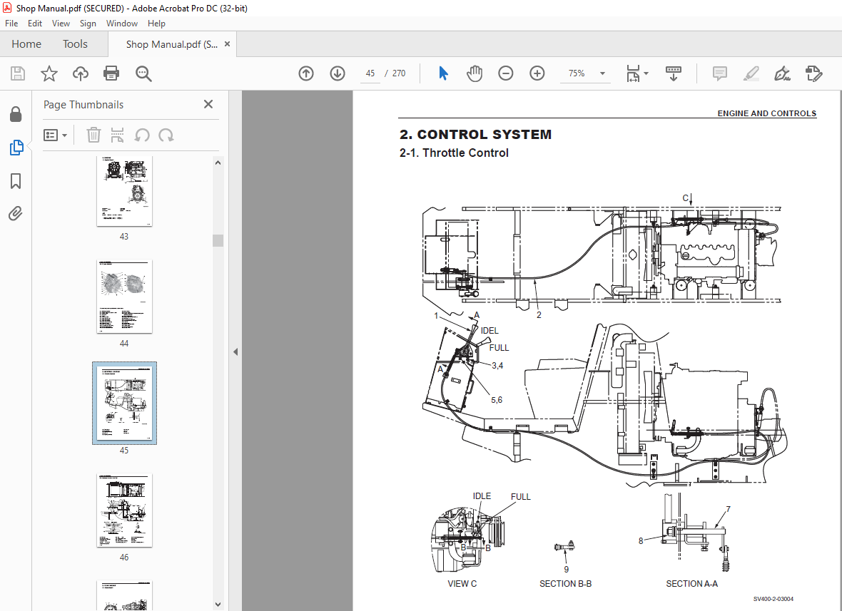
TABLE OF CONTENTS:
Sakai Soil Roller SV410-2 SHOP MANUAL – PDF DOWNLOAD
1 SAFETY
1 GENERAL SAFETY
1-1 Understanding the Safety Symbols and Words 1-001
1-2 General 1-001
1-3 Qualifications of Operators and Maintenance Personnel 1-002
1-4 Safety Practices and Policies 1-002
1-5 Pre Start Inspection 1-003
1-6 Safety Instructions 1-003
1-7 Starting 1-004
1-8 Operating 1-004
1-9 Stopping 1-004
1-10 Maintenance 1-005
1-11 Transporting the Machine 1-007
2 SPECIFICATIONS
1 SPECIFICATION DATA
1-1 SV410D-2 2-001
1-2 SV410T-2 2-003
1-3 SV410TF-2 2-005
1-4 SV410TB-2 2-007
1-5 SV410FB-2 2-009
2 TABLE OF STANDARD VALUES
2-1 Engine 2-011
2-2 Propulsion 2-011
2-3 Hydraulic Systems 2-011
2-4 Steering Devices 2-012
2-5 Brakes 2-012
2-6 Capacities 2-012
3 FUEL AND LUBRICANTS SPECIFICATION
3-1 Rating 2-013
3-2 Recommended Lubricants 2-013
4 TIGHTENING TORQUE CHART 2-014
SV410-2 ○0
3 ENGINE AND CONTROLS
1 ENGINE
1-1 Engine Mount 3-001
1-2 Engine Exterior 3-002
2 CONTROL SYSTEM
2-1 Throttle Control 3-003
2-2 Forward-reverse Control 3-004
3 PUMP MOUNT
3-1 Pump Mount 3-005
3-2 Installation of Pump 3-006
4 HYDRAULIC SYSTEMS
1 SYSTEM CIRCUIT DIAGRAM
1-1 Graphic Symbols for Hydraulic Circuits 4-001
1-2 Hydraulic Circuit Diagram 4-003
1-2-1 Hydraulic circuit diagram (SV410D-2, T-2, TF-2) 4-003
1-2-2 Hydraulic circuit diagram (SV410TB-2, FB-2) 4-004
2 PROPULSION HYDRAULIC SYSTEM
2-1 Propulsion Hydraulic Piping 4-005
2-1-1 Propulsion hydraulic piping (Front) 4-005
2-1-2 Propulsion hydraulic piping (Rear) 4-006
2-2 Hydraulic Component Specifications 4-007
2-2-1 Hydraulic pump assembly (propulsion + vibrator • steering)
(SV410D-2, T-2, TF-2) 4-007
2-2-2 Hydraulic pump assembly (propulsion + vibrator • steering)
(SV410TB-2, TF-2) 4-009
2-2-3 Propulsion hydraulic motor (Front) 4-011
2-2-4 Gear box 4-012
2-2-5 Propulsion hydraulic motor (Rear) 4-014
2-2-6 Servo bypass solenoid valve 4-015
3 VIBRATOR HYDRAULIC SYSTEM
3-1 Vibrator Hydraulic Piping 4-016
3-2 Hydraulic Component Specification 4-017
3-2-1 Vibrator hydraulic motor 4-017
4 STEERING SYSTEM
4-1 Steering Hydraulic Piping 4-018
4-1-1 Steering hydraulic piping (SV410D-2, T-2, TF-2) 4-018
4-1-2 Steering hydraulic piping (SV410TB-2, FB-2) 4-019
SV410-2 ○0
4-2 Steering Wheel 4-020
4-3 Hydraulic Component Specifications 4-021
4-3-1 Orbitrol 4-021
4-3-2 Valve (SV410TB-2, FB-2) 4-022
4-4 Frame (Center Pin) 4-023
5 BLADE SYSTEM (SV410TB-2, FB-2)
5-1 Blade Hydraulic Piping 4-024
5-2 Hydraulic Component Specification 4-025
5-2-1 Valve 4-025
5 ELECTRICAL SYSTEM
1 Precautions for wor k
1-1 W ire Numbers, Wire Sizes, Wire Colors and Connectors Shown
in Electrical Circuit Diagram, Wiring Harness Layout and Wiring Harnesses 5-001
2 SYSTEM CIRCUIT DIAGRAM
2-1 Electrical Circuit Diagram 5-003
3 ELECTRICAL COMPONENTS
3-1 Battery Layout 5-004
3-2 Wiring Harness Layout – Type 1-(1) 5-005
3-3 Wiring Harness Layout – Type 1-(2) 5-006
3-4 Wiring Harness Layout – Type 2-(1) 5-007
3-5 Wiring Harness Layout – Type 2-(2) 5-008
4 WIRING HARNESSES
4-1 Main Frame Harness 5-009
4-1-1 Main frame harness (type 1 only) 5-009
4-1-2 Main frame harness (type 2 only) 5-011
4-2 Engine Harness 5-013
4-2-1 Engine harness (type 1 only) 5-013
4-2-2 Engine harness (type 2 only) 5-015
4-3 Dashboard Harness 5-017
4-3-1 Dashboard harness (type 1 only) 5-017
4-3-2 Dashboard harness (type 2 only) 5-019
4-4 Starter Switch Harness 5-021
4-5 Vibrator Solenoid Harness 5-022
4-6 Hydraulic Oil Filter Harness 5-023
4-7 Starter Relay Harness (Type 1 only) 5-024
4-8 Rear Motor Solenoid Harness 5-025
4-9 Vibration Select Switch Harness 5-026
SV410-2 ○0
4-10 Parking Brake Switch Harness 5-027
4-11 Front Motor Solenoid Harness 5-028
4-12 Travel Mode Select Switch Harness 5-029
5 ELECTRICAL COMPONENT SPECIFICATIONS
5-1 Fuse Box 5-030
6 VIBRATORY DRUM • REAR AXLE
1 PRECAUTIONS FOR DISASSEMBLY AND REASSEMBLY 6-001
2 VIBRATORY DRUM
2-1 Removal and Installation of Vibratory Drum 6-003
2-1-1 Removal of vibratory drum 6-003
2-1-2 Installation of vibratory drum 6-007
2-2 Vibratory Drum Assembly 6-008
2-3 Disassembly and Reassembly of Vibratory Drum 6-009
2-3-1 Disassembly of vibratory drum 6-009
2-3-2 Reassembly of vibratory drum 6-015
3 AXLE
3-1 Rear Axle (SV410D-2) 6-023
3-2 Rear Axle (SV410T-2, TF-2, TB-2, FB-2) 6-024
3-3 Rear Axle Lubrication 6-025
3-4 Rear Axle Structure 6-026
3-4-1 Center housing 6-026
3-4-2 Differential 6-027
3-4-3 Hub reduction gear 6-028
3-4-4 Brake 6-029
7 BRAKE
1 BRAKE SYSTEM
1-1 Brake Pedal 7-001
2 BRAKE HYDRAULIC PIPING 7-002
3 BRAKE SYSTEM 7-003
4 HYDRAULIC COMPONENT SPECIFICATION
4-1 Brake Solenoid Valve 7-004
8 INSPECTION AND ADJUSTMENT
1 INSPECTION AND ADJUSTMENT
1-1 Safety Precautions for Inspection and Adjustment 8-001
1-2 Preparation for Inspection and Adjustment 8-001
SV410-2 ○0
1-3 Precautions for Inspection and Adjustment 8-001
1-4 Warm-up 8-001
1-5 Inspection and Adjustment of Engine Related Items 8-001
2 MEASUREMENT AND ADJUSTMENT OF PROPULSION CIRCUIT PRESSURE
2-1 Measurement 8-002
2-2 Adjustment 8-003
3 MEASUREMENT AND ADJUSTMENT OF PROPULSION CHARGE CIRCUIT
PRESSURE 8-004
3-1 Measurement 8-005
3-2 Adjustment 8-006
4 MEASUREMENT OF PROPULSION SERVO CIRCUIT PRESSURE
4-1 Measurement 8-007
5 MEASUREMENT OF MACHINE SPEED CHANGE CIRCUIT PRESSURE
5-1 Measurement of Front Propulsion Motor 8-008
5-2 Measurement of Rear Propulsion Motor 8-009
6 MEASUREMENT OF PARKING BRAKE RELEASE PRESSURE
6-1 Measurement 8-010
7 MEASUREMENT AND INSPECTION OF VIBRATOR CIRCUIT PRESSURE
7-1 Measurement 8-011
7-2 Inspection 8-012
8 MEASUREMENT AND ADJUSTMENT OF VIBRATOR CHARGE CIRCUIT
PRESSURE 8-013
8-1 Measurement 8-014
8-2 Adjustment 8-015
9 MEASUREMENT OF VIBRATOR HIGH/LOW CHANGE CIRCUIT PRESSURE
9-1 Measurement 8-016
10 MEASUREMENT AND INSPECTION OF STEERING CIRCUIT PRESSURE
10-1 Measurement 8-017
10-2 Inspection 8-018
11 MEASUREMENT AND INSPECTION OF BLADE CIRCUIT PRESSURE
(SV410TB-2, FB-2)
11-1 Measurement 8-019
11-2 Inspection 8-020
12 MEASUREMENT OF HYDRAULIC PUMP CASE PRESSURE
12-1 Measurement 8-021
13 MEASUREMENT OF PROPULSION MOTOR CASE PRESSURE
13-1 Measurement of Front Propulsion Motor 8-022
13-2 Measurement of Rear Propulsion Motor 8-023
SV410-2 ○0
14 MEASUREMENT OF VIBRATOR MOTOR CASE PRESSURE
14-1 Measurement 8-024
15 ADJUSTMENT OF THROTTLE LEVER LINKAGE
15-1 Adjustment 8-025
16 ADJUSTMENT OF F-R LEVER LINKAGE
16-1 Adjustment 8-026
17 BRAKE ADJUSTMENT
17-1 Manually Releasing the Brake 8-027
17-2 Adjustment after Manual Release of Brake 8-028
17-3 Brake Clearance Adjustment 8-029
9 TROUBLESHOOTING
1 TROUBLESHOOTING
1-1 Safety Precautions for Troubleshooting 9-001
1-2 Important Information for Troubleshooting 9-001
1-3 Before Starting 9-002
1-4 Wire Number and Color Code 9-002
2 ELECTRICAL SYSTEM TROUBLESHOOTING
2-1 When Performing Electrical System Fault Diagnosis 9-003
2-1-1 Precautions to take during electrical circuit fault diagnosis 9-003
2-1-2 Inspection procedures using a tester 9-004
2-1-3 Inspection of electrical system 9-009
2-2 Engine 9-012
2-2-1 Engine will not start (Starter motor does not run) 1/3 9-012
2-2-1 Engine will not start (Starter motor does not run) 2/3 9-014
2-2-1 Engine will not start (Starter motor does not run) 3/3 9-016
2-2-2 Engine will not start (But starter motor runs) 9-018
2-2-3 Engine does not stop running 9-018
2-2-4 No charging 9-018
2-2-5 Starter motor runs even when F-R lever is not at “N”
and parking brake is not applied 9-020
2-2-6 Starting engine is difficult 9-020
2-3 Propulsion 9-022
2-3-1 Machine moves neither forward nor backward 1/2 9-022
2-3-1 Machine moves neither forward nor backward 2/2 9-024
2-3-2 Travel mode cannot be changed 1/2 9-026
2-3-2 Travel mode cannot be changed 2/2 9-028
2-3-3 Brake does not work 9-030
SV410-2 ○0
2-4 Vibration 9-032
2-4-1 No vibration occurs 9-032
2-4-2 Amplitude does not change (Remains either Low or High) 9-034
2-4-3 Vibration mode cannot be switched
(F-R lever vibration switch does not work) 9-036
2-5 Lighting 9-038
2-5-1 Illumination of combination meter does not turn on 9-038
2-5-2 Combination meter warning lamp or indicator lamp is abnormal 9-040
2-5-3 Tachometer reading is abnormal 9-042
2-5-4 Hour meter is abnormal 9-042
2-5-5 Temperature meter is abnormal 9-044
2-5-6 Fuel meter is abnormal 9-044
2-5-7 Hydraulic oil filter warning lamp remains ON 9-046
2-5-8 Engine oil pressure warning lamp remains ON 9-046
2-5-9 Vibration indicator lamp does not light 9-048
2-5-10 Parking brake indicator lamp does not light 9-050
2-5-11 Horn does not sound 9-052
2-5-12 Backup buzzer does not sound 9-052
3 HYDRAULIC SYSTEM TROUBLESHOOTING
3-1 When Performing Hydraulic System Troubleshooting 9-053
3-2 Propulsion System 9-054
3-2-1 Machine moves neither forward nor backward 1/2 9-054
3-2-1 Machine moves neither forward nor backward 2/2 9-055
3-2-2 Machine moves in one direction only (forward or backward) 9-055
3-2-3 Slow machine speed or small drive force 1/2 9-055
3-2-3 Slow machine speed or small drive force 2/2 9-056
3-2-4 Travel mode cannot be switched 9-056
3-2-5 Machine does not stop completely with F-R lever in “N” 9-056
3-2-6 Propulsion system is overheating 9-057
3-2-7 Abnormal noise from propulsion system 9-057
3-3 Vibrator System 9-058
3-3-1 No vibration 9-058
3-3-2 Vibrator frequency is too low 9-059
3-3-3 Amplitude does not switch between high and low 9-059
3-3-4 Vibrator does not stop 9-060
3-3-5 Vibrator system is overheating 9-060
3-3-6 Abnormal noise from vibrator system 9-060
3-4 Steering System 9-061
3-4-1 Steering wheel is hard to turn 9-061
SV410-2 ○0
3-4-2 Steering response is slow 9-061
3-4-3 Steering wheel backlash or play is large 9-062
3-4-4 Steering system is overheating 9-062
3-4-5 Abnormal noise from steering system 9-062
3-5 Blade (SV410TB-2, FB-2) 9-063
3-5-1 Blade up/down operation not possible 9-063
3-5-2 Blade movement is slow or force is small 9-063
3-5-3 Blade floating operation not possible 9-064
3-5-4 Blade hydraulic system is overheating 9-064
3-5-5 Abnormal noise from blade hydraulic system 9-064
More products