$33.95
Sakai SV414 Vibrating Roller Shop Manual – PDF DOWNLOAD
Sakai SV414 Vibrating Roller Shop Manual – PDF DOWNLOAD
The Sakai SV414 Vibrating Roller Shop Manual is crucial for maintenance. Covering SV414 series, it ensures efficient servicing and repairs.
FILE DETAILS:
Sakai SV414 Vibrating Roller Shop Manual – PDF DOWNLOAD
Language : English
Pages :294
Downloadable : Yes
File Type : PDF
DESCRIPTION
Sakai SV414 Vibrating Roller Shop Manual – PDF DOWNLOAD
- Introduction
- This manual provides important information to familiarize you with safe operating and maintenance procedures for your SAKAI roller. Even though you may be familiar with similar equipment you must read and understand this manual before operating or servicing this unit.
- Safety is everyone’s business and it is one of your primary concerns. Knowing the guidelines presented in this manual will help provide for your safety, for the safety of those around you and for the proper operation and maintenance of the machine. Improper operation is dangerous and can result in injury or death. Sakai Heavy Industries cannot foresee all possible circumstances or varying conditions to which the operator, serviceman or machine may be exposed to that might lead to a potential hazard.
- Therefore, the warnings and cautions listed in this manual and those placed on the machine are not intended to be all inclusive and liability for personal injury or damage to equipment or property cannot be assumed. All information, specifications and illustrations in this publication are based on the product information available at the time that the publication was written. The contents may change without prior notice due to modifications of the model
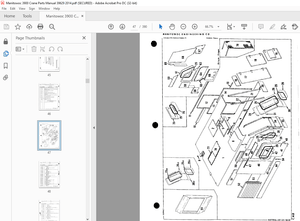
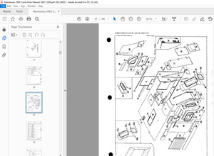
IMAGES PREVIEW OF THE MANUAL:
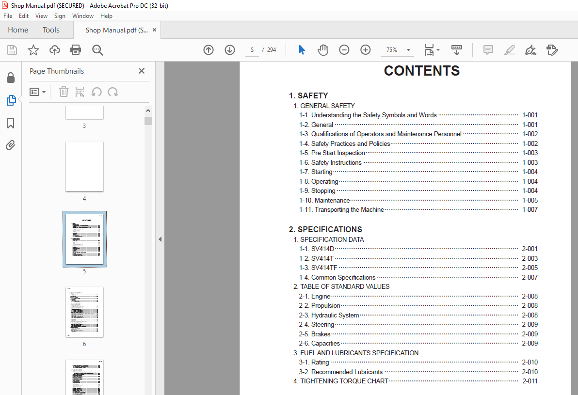
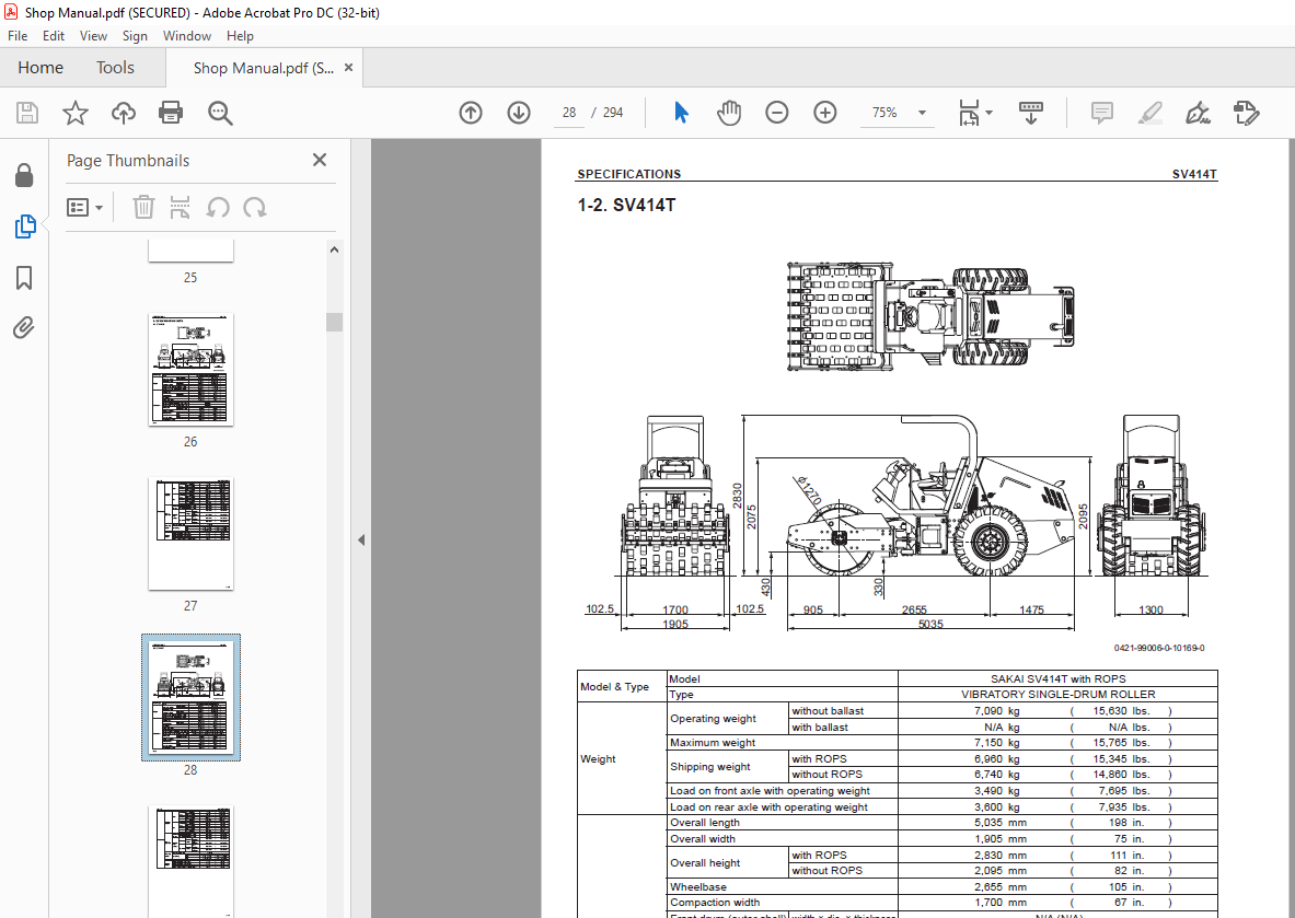
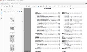
TABLE OF CONTENTS:
Sakai SV414 Vibrating Roller Shop Manual – PDF DOWNLOAD
1. SAFETY
1. GENERAL SAFETY
1-1. Understanding the Safety Symbols and Words 1-001
1-2. General 1-001
1-3. Qualifications of Operators and Maintenance Personnel 1-002
1-4. Safety Practices and Policies 1-002
1-5. Pre Start Inspection 1-003
1-6. Safety Instructions 1-003
1-7. Starting 1-004
1-8. Operating 1-004
1-9. Stopping 1-004
1-10. Maintenance 1-005
1-11. Transporting the Machine 1-007
2. SPECIFICATIONS
1. SPECIFICATION DATA
1-1. SV414D 2-001
1-2. SV414T 2-003
1-3. SV414TF 2-005
1-4. Common Specifications 2-007
2. TABLE OF STANDARD VALUES
2-1. Engine 2-008
2-2. Propulsion 2-008
2-3. Hydraulic System 2-008
2-4. Steering 2-009
2-5. Brakes 2-009
2-6. Capacities 2-009
3. FUEL AND LUBRICANTS SPECIFICATION
3-1. Rating 2-010
3-2. Recommended Lubricants 2-010
4. TIGHTENING TORQUE CHART 2-011
SV414 ○0
0-002
3. ENGINE AND CONTROLS
1. ENGINE
1-1. Engine Mount 3-001
2. FUEL SYSTEM 3-002
3. CONTROL SYSTEM
3-1. Forward-reverse Control 3-004
4. PUMP MOUNT
4-1. Pump Mount 3-005
4-1-1. Installation of pump 3-006
4. HYDRAULIC SYSTEMS
1. SYSTEM CIRCUIT DIAGRAM
1-1. Graphic Symbols for Hydraulic Circuits 4-001
1-2. Hydraulic Circuit Diagram 4-003
2. PROPULSION HYDRAULIC SYSTEM
2-1. Propulsion Hydraulic Piping 4-004
2-1-1. Propulsion hydraulic piping (F) 4-004
2-1-2. Propulsion hydraulic piping (R) 4-005
2-2. Hydraulic Component Specifications 4-006
2-2-1. Hydraulic pump ASSY (propulsion + vibrator + steering • charge) 4-006
2-2-2. Propulsion hydraulic motor (F) 4-008
2-2-3. Gear box 4-010
2-2-4. Propulsion hydraulic motor (R) 4-012
2-2-5. Speed change solenoid valve (F) 4-014
2-2-6. Block (1) 4-015
2-2-7. Block (2) 4-016
2-3. Description and Operation of Propulsion System 4-018
3. VIBRATOR HYDRAULIC SYSTEM
3-1. Vibrator Hydraulic Piping 4-021
3-2. Hydraulic Component Specifications 4-022
3-2-1. Vibrator hydraulic motor 4-022
3-3. Description and Operation of Vibrator System 4-024
4. STEERING SYSTEM
4-1. Steering Hydraulic Piping 4-025
4-2. Steering Wheel 4-026
4-3. Hydraulic Component Specifications 4-027
4-3-1. Orbitrol 4-027
SV414 ○0
0-003
4-4. Description and Operation of Steering System 4-029
4-4-1. Description and operation of steering system 4-029
4-4-2. Structure and operation of Orbitrol 4-030
5. ELECTRICAL SYSTEM
1. Precautions for wor k
1-1. Wire Numbers, Wire Sizes, Wire Colors and Connectors Shown in Electrical
Circuit Diagram, Wiring Harness Layout and Wiring Harnesses 5-001
1-2. Electrical Equipment Installation 5-002
2. SYSTEM CIRCUIT DIAGRAM
2-1. Electrical Circuit Diagram 5-003
3. ELECTRICAL COMPONENTS
3-1. Wiring Harness Layout (1) 5-004
3-2. Wiring Harness Layout (2) 5-005
4. WIRING HARNESSES
4-1. Frame Harness (1) 5-006
4-2. Frame Harness (2) 5-008
4-3. Panel Harness 5-010
4-4. Fuse • Relay Box Assembly 5-012
4-5. Battery Relay Harness 5-014
4-6. Stater Switch Harness 5-016
4-7. Control Switch Harness 5-017
4-8. Throttle Switch Harness 5-018
4-9. Vibration Switch Harness 5-019
4-10. Control Harness 5-020
4-11. F-R Lever Vibration Switch Harness 5-021
4-12. Speed Change Solenoid Harness 5-022
4-13. Vibrator Solenoid Harness 5-023
4-14. Diagnostic Switch Harness 5-024
4-15. Hydraulic Oil Filter Harness 5-025
4-16. Engine Harness 5-026
4-17. Backup Buzzer Harness 5-027
5. ELECTRICAL COMPONENT SPECIFICATIONS
5-1. Fuse Box 5-028
5-2. Combination Meter 5-029
More products