$33.95
Sakai SV505-1 Series Vibrating Roller Shop Manual - PDF
Sakai SV505-1 Series Vibrating Roller Shop Manual – PDF DOWNLOAD
The Sakai SV505-1 Series Vibrating Roller Shop Manual is indispensable for maintenance. Covering SV505-1 rollers, it ensures efficient servicing and repairs.
FILE DETAILS:
Sakai SV505-1 Series Vibrating Roller Shop Manual – PDF DOWNLOAD
Language : English
Pages : 410
Downloadable : Yes
File Type : PDF
DESCRIPTION
Sakai SV505-1 Series Vibrating Roller Shop Manual – PDF DOWNLOAD
How to Use the Manual
Prior to operation of the compactor read the following sections:
• Introduction
• System Identification
• Familiarization.
Use the Maintenance section to schedule and perform maintenance. The maintenance is performed at the
following intervals:
• Every 10 hours or daily
• Every 50 hours
• Every 250 hours
• Every 500 hours
• Every 1000 hours.
- Refer to the Operation and Maintenance Manual QSB4.5 and QSB6.7, Bulletin 4021531 for Cummins® Engine maintenance schedule. When a compactor issue has been identified use the Troubleshooting section of this manual. The troubleshooting section is divided into procedures that are symptom driven.
- Each of the individual procedures is designed to troubleshoot the most likely problem area first. When the problem area is identified the procedure will refer you to the appropriate disassembly and assembly procedure. To troubleshoot Cummins® Engine electrical problems refer to the Troubleshooting and Repair Manual CM850 Electronic Control System ISB, ISBe4, QSB4.5, QSB5.9, QSB6.7, ISC, QSC8.3, ISL and QSL9 Engines, Bulletin 4021416.
- To troubleshoot Cummins® engine mechanical problems refer to the Service Manual ISB, ISBe4 and QSB (Common Rail Fuel System) Series Engines, Bulletin 4021271. Cummins® QSB4.5, QSB6.7, QSC8.3, and QSL9 CM850 Electronic Control Module Wiring Diagram, Bulletin 4021524 is needed to troubleshoot engine electronic issues. The Compactor Repair Section supplies direction with illustration to remove, clean and inspect for reuse, disassemble, assemble and install individual compactor components.
- The schematic section has hydraulic schematics and electrical wiring diagrams for troubleshooting use. The troubleshooting trees will refer to the wiring diagram or hydraulic schematic. Component and wire terminology are consistent throughout the manual. A specification section has been provided to aid in repair
IMAGES PREVIEW OF THE MANUAL:
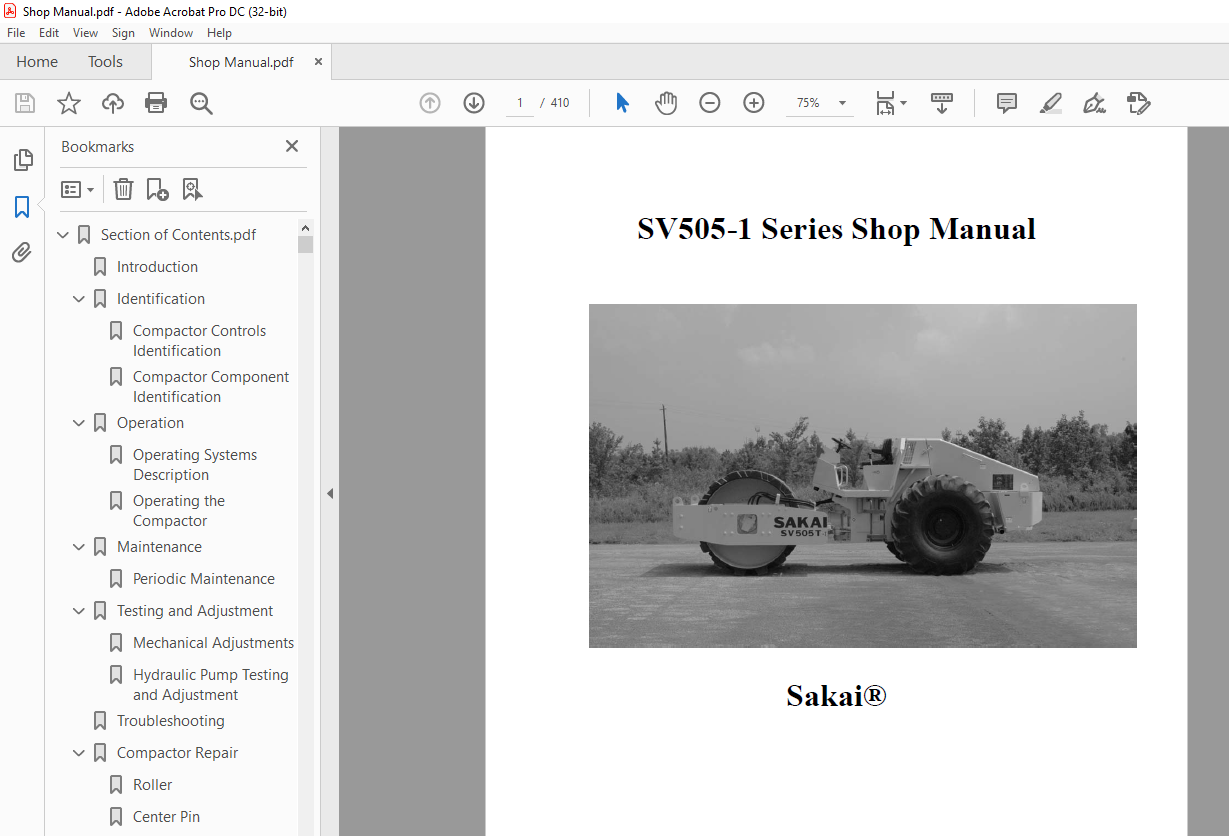
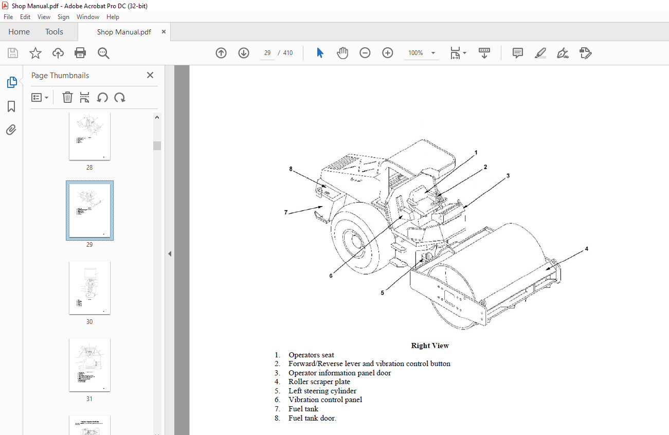
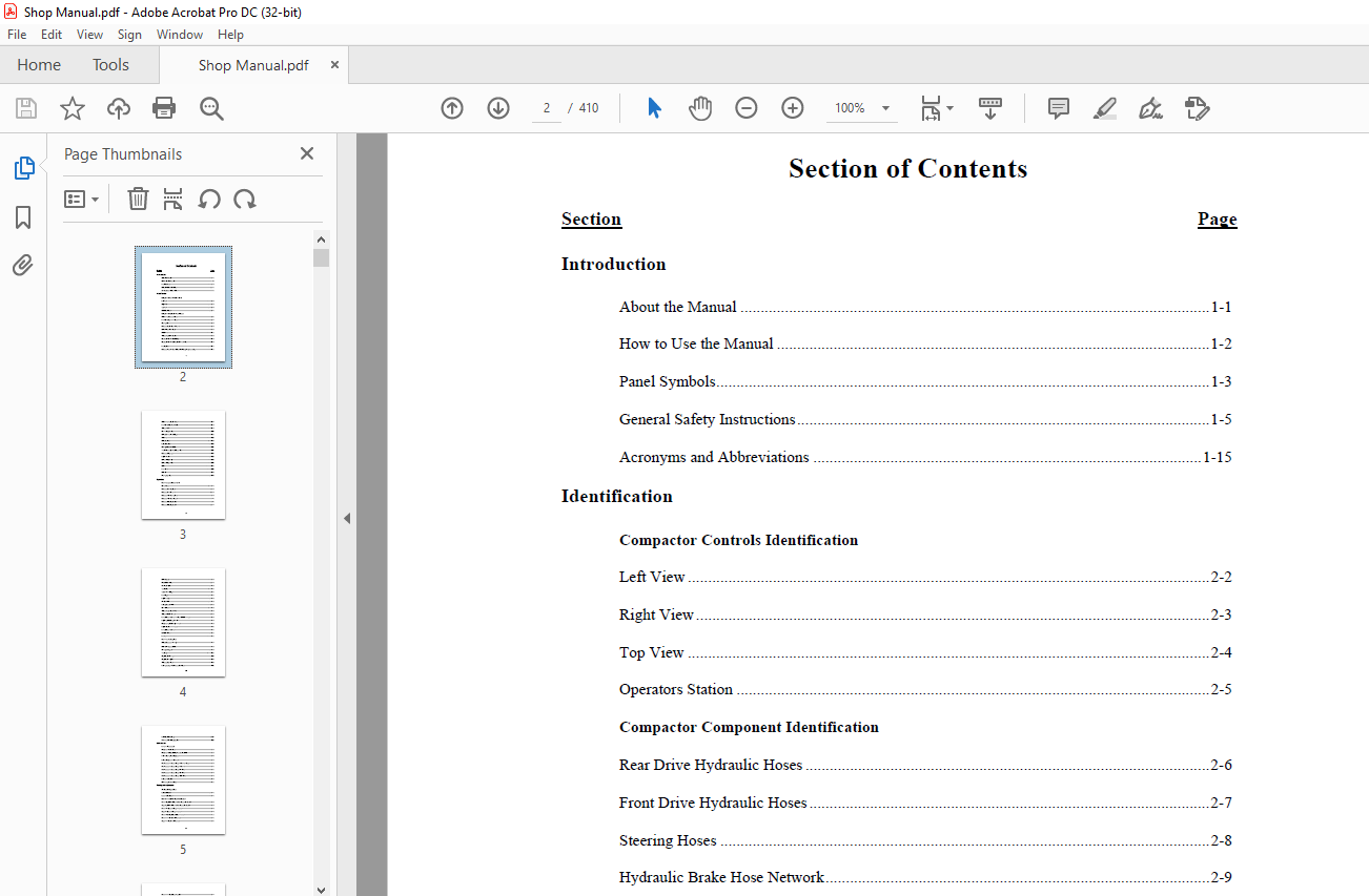
TABLE OF CONTENTS:
Sakai SV505-1 Series Vibrating Roller Shop Manual – PDF DOWNLOAD
Section Page
Introduction
About the Manual 1-1
How to Use the Manual 1-2
Panel Symbols1-3
General Safety Instructions1-5
Acronyms and Abbreviations 1-15
Identification
Compactor Controls Identification
Left View 2-2
Right View2-3
Top View 2-4
Operators Station 2-5
Compactor Component Identification
Rear Drive Hydraulic Hoses 2-6
Front Drive Hydraulic Hoses 2-7
Steering Hoses 2-8
Hydraulic Brake Hose Network2-9
Brake Pedal and Linkage 2-10
Center Pin 2-11
Vibrator Hydraulic Hoses 2-12
Drum and Vibrator (Model D)2-13
Drum and Vibrator Motor (Model T and TF) 2-14
Fuel System2-15
Hydraulic Propulsion, Vibrator and Steering Pump Assembly2-16
i
Rear Drive Propulsion Motor2-17
Front Drive Propulsion Motor 2-18
Vibrator Motor2-19
Electric Components2-20
Instrument Panel and Relays2-21
Rear Axle 2-22
Intake System2-23
Exhaust System2-24
Cooling Hose and Radiator2-25
Travel Controls (Forward/Reverse) 2-26
Hydraulic Coupling2-27
Engine Mount 2-28
Differential (1of 2)2-29
Differential (2 of 2)2-30
Brake2-31
Final Drive 2-32
Orbitrol2-33
Steering Cylinder 2-34
Operation
Operating Systems Description
Diesel Engine3-1
Hydraulic Drive System3-2
Hydraulic Drive Circuit 3-3
Hydraulic Vibratory System 3-4
Hydraulic Vibratory Circuit 3-5
Hydraulic Steering System3-6
Hydraulic Steering Circuit 3-7
ii
Brake System 3-8
Combination Meter 3-9
Monitor Display3-10
Tachometer 3-11
Temperature Gauge3-11
Fuel Gauge3-11
Engine Lamps 3-12
Starter Switch3-12
Parking Brake Switch 3-12
Horn Button 3-13
Vibrator Amplitude Switch3-13
Vibrator Selector Switch3-13
Forward/Reverse Lever Vibration ON/OFF Switch 3-14
Engine Speed Change Switch 3-14
Compactor Speed Change Switch3-14
Engine Diagnostic Switches 3-15
Forward/Reverse Lever3-15
Unloader Valve 3-15
Fuse Box 3-16
Operating the Compactor
Release Brakes for Towing3-17
Before Starting Inspection 3-18
Starting the Engine3-19
Traveling3-21
Stopping and Parking3-22
Stopping the Engine3-23
Vibratory Operation 3-23
Loading Using a Winch Equipped Trailer 3-25
ii i
Self Propelled Loading 3-27
Working With the Compactor3-28
Maintenance
Periodic Maintenance
Compactor Maintenance 4-2
Compactor Component Replacement Schedule4-2
Prior to Starting the Compactor 4-3
Lifting Compactor with Hoist 4-4
Maintenance Procedures Every 10 Hours or Daily4-4
Maintenance Procedures Every 50 Hours4-5
Maintenance Procedures Every 250 Hours4-6
Maintenance Procedures Every 500 Hours4-9
Maintenance Procedures Every 1,000 Hours4-9
Long Term Storage 4-14
Connecting Booster Cable 4-15
Testing and Adjustment
Mechanical Adjustments
Seat Adjustment 5-1
Scraper Adjustment5-1
Hydraulic Pump Testing and Adjustment
Measure Hydraulic Pressure Main Propulsion Circuit5-2
Adjust Hydraulic Pressure Main Propulsion Circuit5-3
Measure Propulsion Charge Pressure 5-4
Adjust Propulsion Charge Pressure 5-4
Measure Parking Brake Release Pressure 55
Measure Vibrator Circuit Pressure5-5
Adjust Vibrator Circuit Pressure5-6
iv
Measure Vibrator Charge Pressure 5-7
Adjust Vibrator Charge Pressure 5-8
Measure Steering Circuit Pressure5-9
Adjust Forward/Reverse Cable 5-10
Troubleshooting
Troubleshooting Guidelines6-1
Wiring Diagram Color Codes 6-2
Engine Warning Lamp is Illuminated 6-4
Engine Stop Lamp is Illuminated6-8
Wait to Start Lamp is Illuminated6-12
Vibration Lamp Does Not Illuminate When Vibration Engaged6-16
Parking Brake Lamp Does Not Illuminate When Parking Brake Engaged 6-25
Engine Oil Pressure Lamp Illuminated 6-29
Hydraulic Oil Filter Lamp Illuminated 6-34
Tachometer Does Not Indicate Engine Speed 6-39
Hour Meter Does Not Work 6-49
Coolant Temperature Gauge Does Not Work6-55
Fuel Gauge Does Not Work6-60
Backup Alarm Does Not Work6-64
Horn Does Not Work6-71
Compactor Steering Malfunction6-80
Vibration Does Not Work6-85
Low Amplitude Vibration Setting Does Not Work 6-98
High Amplitude Vibration Setting Does Not Work6-104
Can Not Turn Vibration From Forward/Reverse Lever6-110
Compactor Will Not Start 6-116
Engine Will Not Idle Correctly6-134
v
Engine Will Not Reach MID Speed6-139
Engine Will Not Reach Full Speed 6-144
Compactor Will Not Move Forward and/or Reverse or Does Not Drive Correctly 6-151
Parking Brake Does Not Work 6-158
Compactor Will Not Change Speeds 6-166
Compactor Repair
Roller
Remove 7-1
Disassemble (Vibratory Motor Side) 7-4
Disassemble (Drive Motor Side)7-9
Clean and Inspect for Reuse 7-12
Assemble (Drive Motor) 7-16
Assemble (Vibratory Motor)7-20
Install 7-27
Center Pin
Remove 7-29
Disassemble 7-30
Clean 7-32
Assemble7-32
Install 7-36
Operators Station
Remove 7-38
Install 7-40
Manual Vibration Control Switch
Remove 7-42
Install 7-43
v i
Vibratory Control Panel Switches
Remove 7-43
Install 7-44
Combination Meter
Remove 7-45
Install 7-46
Parking Brake Button
Remove 7-48
Install 7-48
Engine Status Lamps
Remove 7-49
Install 7-50
Engine Start Switch
Remove 7-51
Install 7-51
Directional Control Lever Cable
Remove 7-54
Install 7-55
Directional Control Lever Micro-Switches
Remove 7-56
Disassemble 757
Assemble7-57
Install 7-58
Foot Brake Switch
Remove 7-58
Disassemble 7-59
Assemble7-59
Install 7-59
v ii
Speed Sensor (Combination Meter Tachometer)
Remove 7-60
Install 7-60
Coolant Temperature Sensor (Combination Meter Temperature Gauge)
Remove 7-61
Install 7-62
Fuel Level Sensor (Combination Meter Fuel Level Gauge)
Install 7-62
Remove 7-63
Battery Relay
Remove 7-63
Install 7-64
Operator’s Station Relay and Diodes
Remove 7-65
Install 7-65
Horn
Remove 7-66
Install 7-66
Hydraulic Oil Filer Switch
Remove 7-66
Install 7-66
Tachometer Control Box
Remove 7-67
Install 7-67
vi ii
Radiator and Cooling System
Remove 7-67
Install 7-69
Hydraulic Tank
Remove 7-71
Install 7-72
Engine and Pump Assembly
Remove 7-73
Disassemble 7-78
Assemble7-80
Install 7-83
Rear End
Remove 7-90
Install 7-91
Back Up Alarm
Remove 7-92
Install 7-93
Starter Relay
Remove 7-93
Install 7-94
Engine Speed Change Switch
Remove 7-94
Install 7-95
Forward/Reverse Lever Vibration Switch
Remove 7-96
Install 7-97
ix
Fuses 65 Amp and Above
Remove 7-98
Install 7-98
Parking Brake Valve
Remove 7-98
Install 7-99
Vibration Amplitude Solenoid
Remove 7-99
Install 7-100
Compactor Speed Solenoid
Remove 7-100
Install 7-101
Orbitrol Steering Valve
Remove 7-101
Install 7-102
Schematics
Electrical 8-1
Hydraulic 8-2
Service Literature
Additional Service Literature9-1
Specifications
Compactor General Specifications10-1
Compactor Overall Specifications 10-4
Overall Coolant Levels 10-4
Battery Electrolyte Reading 10-4
Compactor Capacity10-4
x
x i
Fuel Oil and Grease Rating10-5
Recommended Lubricants10-5
Rear Drive Specifications 10-6
Hydraulic Motor Specifications 10-7
Metric to US Torque 10-8
Fraction to Decimal to Millimeter Conversions10-9
Metric Drill and Tap Chart10-11
Weights and Measures Conversion Factors 10-15
More products