$38
Sakai SW770 Shop Manual 3498-6431 A-0 – PDF DOWNLOAD
Sakai SW770 Shop Manual 3498-6431 A-0 – PDF DOWNLOAD
FILE DETAILS:
Sakai SW770 Shop Manual 3498-6431 A-0 – PDF DOWNLOAD
Language : English
Pages :400
Downloadable : Yes
File Type : PDF
TABLE OF CONTENTS:
Sakai SW770 Shop Manual 3498-6431 A-0 – PDF DOWNLOAD
1 SAFETY
1 GENERAL SAFETY
1-1 Understanding the Safety Symbols and Words 1-001
1-2 General 1-001
1-3 Qualifications of Operators and Maintenance Personnel 1:002
1-4 Safety Practices and Policies 1-002
1-5 Pre Start Inspection 1-003
1-6 Safety Instructions 1-003
1-7 Starting 1-004
1-8 Operating 1-004
1-9 Stopping 1-004
1-10 Maintenance 1-005
1-11 Transporting the Machine 1-007
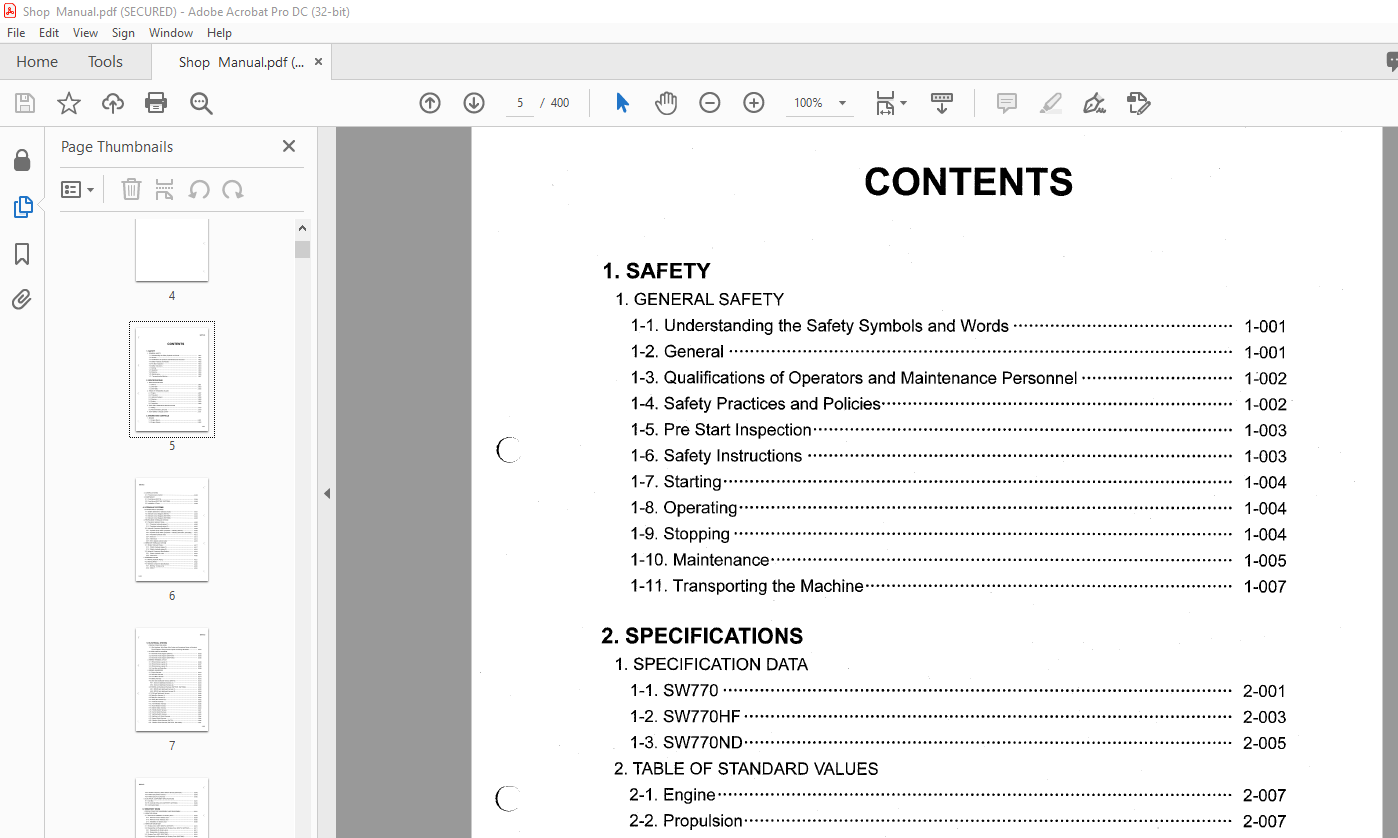
2 SPECIFICATIONS
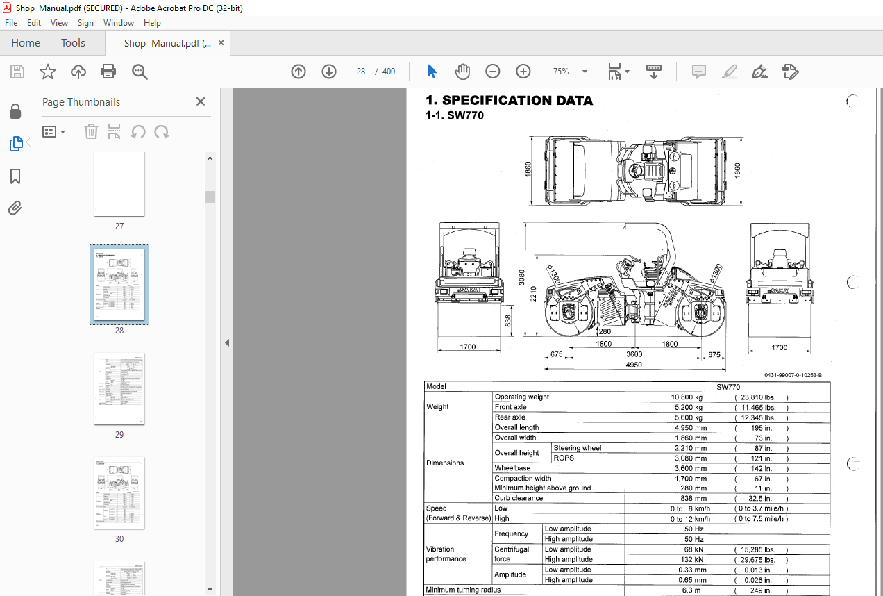
1 SPECIFICATION DATA
1-1 SW770 2-001
1-2 SW770HF 2-003
1-3 SW770ND 2-005
2 TABLE OF STANDARD VALUES
2-1 Engine 2-007
2-2 Propulsion 2-007
2-3 Hydraulic Systems 2-008
2-4 Steering 2-008
2-5 Brakes 2-009
2-6 Capacities 2-009
3 FUELAND LUBRICANTS SPECIFICATION
3-1 Rating 2-01 O
3-2 Recommended Lubricants 2-01 O
4 TIGHTENING TORQUE CHART– 2-011
3 ENGINE AND CONTROLS
1 ENGINE
1-1 Engine Mount 3-001
1-2 Engine Exterior 3-002
2 CONTROL SYSTEM
2-1 Forward-reverse Control 3-003
3 PUMP MOUNT
3-1 Pump Mount (SW770) 3-004
3-2 Pump Mount (SW770HF, SW770ND) 3-005
3-3 Installation of Pump 3-006
4 HYDRAULIC SYSTEMS
1 SYSTEM CIRCUIT DIAGRAM
1-1 Graphic Symbols for Hydraulic Circuits 4-001
1-2 Hydraulic Circuit Diagram (SW770) 4-003
1-3 Hydraulic Circuit Diagram (SW770HF) 4-004 C
1-4 Hydraulic Circuit Diagram (SW770ND) 4-005
2 PROPULSION HYDRAULIC SYSTEM
2-1 Propulsion Hydraulic Piping 4-006
2-1-1 Propulsion hydraulic piping (1) 4-006
2-1-2 Propulsion hydraulic piping (2) 4-007
2-2 Hydraulic Component Specifications 4-008
2-2-1 Hydraulic pump ASSY (propulsion + vibrator) (SW770) 4-008
2-2-2 Hydraulic pump ASSY (propulsion+ vibrator) (SW770HF, SW770ND) 4-010
2-2-3 Propulsion hydraulic motor 4-012
2-2-4 Gear box 4-013
2-2-5 Valve block 4-014
2-2-6 Servo bypass solenoid valve 4-016
3 VIBRATOR HYDRAULIC SYSTEM (
3-1 Vibrator Hydraulic Piping 4-017
3-1-1 Vibrator hydraulic piping (1) 4-017
3-1-2 Vibrator hydraulic piping (2) 4-018
3-2 Hydraulic Component Specifications 4-019
3-2-1 Vibrator hydraulic motor 4-019
3-2-2 Valve block 4-020
4 STEERING SYSTEM
4-1 Steering Hydraulic Piping 4-021
4-2 Steering Wheel 4-022
4-3 Hydraulic Component Specifications 4-023
4-3-1 Steering• charge pump 4-023
4-3-2 Orbitrol 4-024
5 ELECTRICAL SYSTEM
1 PRECAUTIONS FOR WORK
1-1 Wire Numbers, Wire Sizes, Wire Colors and Connectors Shown in Electrical
Circuit Diagram, Wiring Harness Layout and Wiring Harnesses 5-001
2 SYSTEM CIRCUIT DIAGRAM
2-1 Electrical Circuit Diagram (SW770) 5-003
2-2 Electrical Circuit Diagram (SW770HF) 5-004
2-3 Electrical Circuit Diagram (SW770ND) 5-005
3 WIRING HARNESS LAYOUT
3-1 Wiring Harness Layout (1 ) 5-006
3-2 Wiring Harness Layout (2) 5-007
3-3 Wiring Harness Layout (3) 5-008
3-4 Fuse Box and Relay Box 5-009
4 WIRING HARNESSES
4-1 Engine Harness 5-01 O
4-2 Rear Main Harness 5-012
4-3 Front Main Harness 5-014
4-4 Battery Harness 5-016
4-5 Deck and Dashboard Harness (SW770) 5-018
4-5-1 Deck and dashboard harness (1) 5-018
4-5-2 Deck and dashboard harness (2) 5-020
4-6 SODAS and Dashboard Harness (SW770HF, SW770ND) 5-022
4-6-1 BO DAS and dashboard harness (1 ) 5-022
4-6-2 SODAS and dashboard harness (2) 5-024
4-7 ECM and Dashboard Harness 5-026
4-8 Relay Box Harness (1 ) 5-028
4-9 Relay Box Harness (2) 5-030
4-10 Relay Box Harness (3) 5-032
4-11 Fuse Box Harness 5-034
4-12 Front Member Harness 5-036
4-13 Rear Member Harness 5-038
4-14 Starter Switch Harness 5-040
4-15 Throttle Switch Harness 5-041
4-16 Control Switch Harness 5-042
4-17 Lighting Switch Harness 5-043
4-18 Lighting Lo-Hi Switch Harness 5-044
4-19 Hazard Switch Harness 5-045
4-20 Vibration Switch Harness (SW770) 5-046
4-21 Vibration Switch Harness (SW770HF, SW770ND) 5-047
4-22 Vibration Frequency Select Switch Harness (SW770HF) 5-048
4-23 Water Spray Switch Harness 5-049
4-24 Water Spray Pump Harness 5-050
5 ELECTRICAL COMPONENT SPECIFICATIONS
5-1 Fuse Box 5-051
5-2 RC Controller (RC2-2/21) (SW770HF, SW770ND) 5-052
5-3 Combination Meter5-054
6 VIBRATORY DRUM
1 PRECAUTIONS FOR DISASSEMBLY AND REASSEMBLY6-001
2 VIBRATORY DRUM
2-1 Removal and Installation of Vibratory Drum
2-1-1 Removal of front vibratory drum
2-1-2 Removal of rear vibratory drum
2-1-3 Installation of vibratory drum
3 VIBRATORY DRUM ASSY
3-1 Vibratory Drum ASSY (SW770, SW770HF)
3-2 Disassembly and Reassembly of Vibratory Drum (SW770, SW770HF)
3-2-1 Disassembly of vibratory drum
3-2-2 Reassembly of vibratory drum
3-3 Vibratory Drum ASSY (SW770ND)
3-4 Disassembly and Reassembly of Vibratory Drum (SW770ND)
3-4-1 Disassembly of vibratory drum
3-4-2 Reassembly of vibratory drum
1 BRAKE PEDAL 7-001
2 BRAKE SYSTEM?-002
8 WATER SPRAY SYSTEM
1 WATER SPRAY SYSTEM
1-1 Water Spray Piping (1 )8-001
1-2 Water Spray Piping (2) 8-002
9 INSPECTION AND ADJUSTMENT
1 INSPECTION AND ADJUSTMENT
1-1 Safety Precautions for Inspection and Adjustment 9-001
1-2 Preparation for Inspection and Adjustment 9-001
1-3 Precautions for Inspection and Adjustment 9-001
1-4 Warm-up 9-001
1-5 Inspection and Adjustment of Engine Related Items 9-001
2 MEASUREMENT AND ADJUSTMENT OF PROPULSION CIRCUIT PRESSURE
(SW770)
2-1 Measurement 9-002
2-2 Adjustment 9-003
2-2-1 If pressures on both forward and reverse sides deviate from maximum circuit
pressure range by same value 9-003
2-2-2 If pressure on either forward or reverse side deviates from maximum circuit
pressure range 9-004
3 MEASUREMENT AND ADJUSTMENT OF PROPULSION CIRCUIT PRESSURE
(SW770HF, SW770ND)
3-1 Measurement 9-005
3-2 Adjustment 9-006
3-2-1 If pressures on both forward and reverse sides deviate from maximum circuit
pressure range by same value 9-006
3-2-2 If pressure on either forward or reverse side deviates from maximum circuit
pressure range 9-007
4 MEASUREMENT AND ADJUSTMENT OF PROPULSION/ VIBRATOR CHARGE
CIRCUIT PRESSURE (SW770)
4-1 Measurement 9-008
4-2 Adjustment 9-009
5 MEASUREMENT AND ADJUSTMENT OF PROPULSION/ VIBRATOR CHARGE
CIRCUIT PRESSURE (SW770HF, SW770ND)
5-1 Measurement 9-01 O
5-2 Adjustment 9-011
6 MEASUREMENT OF MACHINE HIGH/LOW SPEED CHANGE CIRCUIT PRESSURE
6-1 Measurement 9-012
7 MEASUREMENT OF PROPULSION SERVO CIRCUIT PRESSURE
(SW770)
7 -1 Measurement 9-013
8 MEASUREMENT OF PROPULSION SERVO CIRCUIT PRESSURE
(SW770HF, SW770ND)
8-1 Measurement 9-014
9 MEASUREMENT OF PARKING BRAKE RELEASE PRESSURE
9-1 Measurement 9-015
0-005
SW770®
10 MEASUREMENT AND ADJUSTMENT OF VIBRATOR CIRCUIT PRESSURE
(SW770)
10-1 Measurement 9-016
10-2 Adjustment 9-017
10-2-1 If pressures on both Low amplitude and High amplitude sides deviate from
maximum circuit pressure range by same value 9-017
10-2-2 If pressure on either Low amplitude or High amplitude side deviates from
maximum circuit pressure range 9-018
11 MEASUREMENT AND ADJUSTMENT OF VIBRATOR CIRCUIT PRESSURE
(SW770HF, SW770ND)
11-1 Measurement 9-019
11-2 Adjustment 9-020 (_
11-2-1 If pressures on both Low amplitude/Normal and High amplitude/
Horizontal sides deviate from maximum circuit pressure range by
same value 9-020
11-2-2 If pressure on either Low amplitude/Normal or High amplitude/
Horizontal side deviates from maximum circuit pressure range 9-021
12 MEASUREMENT AND INSPECTION OF STEERING CIRCUIT PRESSURE
12-1 Measurement 9-022
12-2 Inspection 9-023
13 MEASUREMENT OF HYDRAULIC PUMP CASE PRESSURE (SW770)
13-1 Measurement of Propulsion Pump Case Pressure 9-024
13-2 Measurement of Vibrator Pump Case Pressure 9-025
14 MEASUREMENT OF HYDRAULIC PUMP CASE PRESSURE (SW770HF, SW770ND)
14-1 Measurement of Propulsion Pump Case Pressure 9-026
14-2 Measurement of Vibrator Pump Case Pressure 9-027
15 MEASUREMENT OF PROPULSION MOTOR CASE PRESSURE
15-1 Measurement 9-028
16 MEASUREMENT OF VIBRATOR MOTOR CASE PRESSURE (SW770, SW770HF)
16-1 Measurement 9-029
17 MEASUREMENT OF VIBRATOR MOTOR CASE PRESSURE (SW770ND)
17-1 Measurement • 9-030
18 ADJUSTMENT OF F-R LEVER LINKAGE
18-1 Adjustment 9-031
10 TROUBLESHOOTING
1 TROUBLESHOOTING
1-1 Safety Precautions for Troubleshooting 10-001
1-2 Important Information for Troubleshooting 10-001
1-3 Before Starting 10-002
2 ELECTRICAL SYSTEM TROUBLESHOOTING
2-1 When Performing Electrical System Fault Diagnosis 10-003
2-1-1 Precautions to take during electrical circuit fault diagnosis 10-003
2-1-2 Inspection procedures using a tester 10-004
2-1-3 Inspection of electrical system 10-009
2-2 Engine Diagnosis Trouble Code 10-011
2-2-1 Description of diagnostic trouble code (OTC) 10-011
2-2-2 Table of the diagnostic trouble code (DTC) 10-013
2-3 Vibration Error Lamp (SW770HF, SW770ND) 10-016
2-4 Engine 10-018
2-4-1 Engine will not start (Starter motor does not run) 1/3 10-018
2-4-1 Engine will not start (Starter motor does not run) 2/3 10-020
2-4-1 Engine will not start (Starter motor does not run) 3/3 10-022
2-4-2 Engine will not start (But starter motor runs) 10-024
2-4-3 No charging 10-026
2-4-4 Glow plug is not heated
(Engine starting performance is bad in cold weather) 10-026
2-4-5 Engine speed cannot be switched 10-028
2-4-6 Starter motor runs even when F-R lever is not at “N” and
parking brake is not applied 10-028
2-5 Propulsion 10-030
2-5-1 Machine moves neither forward nor backward 1/3 10-030
2-5-1 Machine moves neither forward nor backward 2/3 10-032
2-5-1 Machine moves neither forward nor backward 3/3 10-034
2-5-2 Machine speed cannot be changed 10-034
2-5-3 Brake does not work 10-036
2-6 Vibration 10-038
2-6-1 No vibration occurs 1/4 10-038
2-6-1 No vibration occurs 2/4 10-040
2-6-1 No vibration occurs 3/4 10-042
2-6-1 No vibration occurs 4/4 10-044
2-6-2 Amplitude does not change
(Remains either low/horizontal or high/normal) 1/3 10-046
2-6-2 Amplitude does not change
(Remains either low/horizontal or high/normal) 2/3 10-048
2-6-2 Amplitude does not change
(Remains either low/horizontal or high/normal) 3/3 10-050
2-6-3 Frequency does not change (Remains either frequency)
(SW770HF) 1/2 ••••10-052
2-6-3 Frequency does not change (Remains either frequency)
(SW770HF) 2/2 10-054
2-6-4 Vibration mode cannot be switched
C’
(F-R lever vibration switch does not work) 10-056 (
2-6-5 Vibratory drum cannot be switched 10-058
2-7 Water Spray 10-060
2-7-1 Continuous water spray does not operate 1/2 10-060
2-7-1 Continuous water spray does not operate 2/2 10-062
2-7-2 Continuous water spray works, but auto water spray does not operate 10-064
2-7-3 Continuous water spray works,
but intermittent water spray does not operate 10-066
2-8 Lighting 10-068
2-8-1 Head lamp, side marker lamp and tail lamp do not light 10-068
2-8-2 Flood lamp does not light 10-070
2-8-3 High-beam of head lamp does not light 10-070
2-8-4 Turn signal lamp does not blink 10-072
2-8-5 Hazard lamp does not light (Turn signal blinks) 10-074 (
2-8-6 Backup lamp does not light10-074
2-8-7 Stop lamp does not light 10-076
2-8-8 Illumination of combination meter does not turn on 10-078
2-8-9 Combination meter warning lamp or indicator lamp is abnormal 10-080
2-8-10 Tachometer reading is abnormal 10-082
2-8-11 Hour meter is abnormal 10-082
2-8-12 Temperature meter is abnormal 10-084
2-8-13 Fuel meter is abnormal 10-084
2-8-14 Hydraulic oil filter warning lamp remains ON 10-086
2-8-15 Engine oil pressure warning lamp remains ON 10-086
2-8-16 Vibration indicator lamp does not light (SW770) 10-088
2-8-17 Vibration indicator lamp does not light (SW770HF, SW770ND) 10-090
2-8-18 Parking brake indicator lamp does not light 10-092
2-8-19 Water spray indicator lamp does not light 10-094
2-8-20 Flood lamp indicator lamp does not light 10-096
2-8-21 Side marker lamp indicator lamp does not light 10-096
2-8-22 Turn signal indicator lamp does not light 10-098
2-8-23 Preheating indicator lamp does not light 10-100
2-8-24 Horn does not sound 10-102
2-8-25 Backup buzzer does not sound 10-102
3 HYDRAULIC SYSTEM TROUBLESHOOTING
3-1 When Performing Hydraulic System Troubleshooting 10-103
3-2 Propulsion System 10-104
3-2-1 Machine moves neither forward nor backward 1/2 10-104
3-2-1 Machine moves neither forward nor backward 2/2 10-105
3-2-2 Machine moves in one direction only (forward or backward) 10-105
3-2-3 Slow machine speed or small drive force 1/2 10-105
3-2-3 Slow machine speed or small drive force 2/2 10-106
3-2-4 Machine speed cannot be switched 10-106
3-2-5 Machine does not stop completely with F-R lever in “N” 10-106
3-2-6 Propulsion system is overheating 10-107
3-2-7 Abnormal noise from propulsion system 10-107
3-3 Vibrator System 10-108
3-3-1 No vibration 1 /2 10-108
3-3-1 No vibration 2/2 10-109
3-3-2 Vibrator frequency is too low 10-109
3-3-3 Vibrator amplitude does not change 10-11 O
3-3-4 Vibratory drum does not changeover vibrating • 10-11 O
3-3-5 Vibrator does not stop 10-11 O
3-3-6 Vibrator system is overheating 10-11 O
3-3-7 Abnormal noise from vibrator system 10-11 O
3-4 Steering System 10-111
3-4-1 Steering wheel is hard to turn 10-111
3-4-2 Steering response is slow 10-111
3-4-3 Steering wheel backlash or play is large 10-112
3-4-4 Steering system is overheating 10-112
3-4-5 Abnormal noise from steering system 10-112
IMAGES PREVIEW OF THE MANUAL:
More products