$36
Sakai SW880-1990-1 Shop Manual 3498-6568A-0 – PDF DOWNLOAD
Sakai SW880-1990-1 Shop Manual 3498-6568A-0 – PDF DOWNLOAD
FILE DETAILS:
Sakai SW880-1990-1 Shop Manual 3498-6568A-0 – PDF DOWNLOAD
Language : English
Pages :428
Downloadable : Yes
File Type : PDF
TABLE OF CONTENTS:
Sakai SW880-1990-1 Shop Manual 3498-6568A-0 – PDF DOWNLOAD
1. SAFETY
1. GENERAL SAFETY
1-1. Understanding the Safety Symbols and Words 1-001
1-2. General 1-001
1-3. Qualifications of Operators and Maintenance Personnel 1-002
1-4. Safety Practices and Policies 1-002
1-5. Pre Start Inspection 1-003
1-6. Safety Instructions 1-003
1-7. Starting 1-004
1-8. Operating 1-004
1-9. Stopping 1-004
1-10. Maintenance 1-005
1-11. Transporting the Machine 1-007
2. SPECIFICATIONS
1. SPECIFICATION DATA
1-1. SW880-1 2-001
1-2. SW990-1 2-004
2. TABLE OF STANDARD VALUES
2-1. Engine 2-007
2-2. Propulsion 2-007
2-3. Hydraulic System 2-007
2-4. Steering 2-008
2-5. Brakes 2-008
2-6. Capacities 2-008
3. FUEL AND LUBRICANTS SPECIFICATION
3-1. Rating 2-009
3-2. Recommended Lubricants 2-009
4. TIGHTENING TORQUE CHART 2-010
SW880-1/990-1 ○0
0-002
3. ENGINE AND CONTROLS
1. ENGINE
1-1. Engine Mount 3-001
2. FUEL SYSTEM 3-002
3. CONTROL SYSTEM
3-1. Forward-reverse Control 3-003
4. PUMP MOUNT
4-1. Pump Mount 3-004
4-1-1. Installation of pump 3-005
4. HYDRAULIC SYSTEMS
1. SYSTEM CIRCUIT DIAGRAM
1-1. Graphic Symbols for Hydraulic Circuits 4-001
1-2. Hydraulic Circuit Diagram 4-003
2. PROPULSION HYDRAULIC SYSTEM
2-1. Propulsion Hydraulic Piping 4-004
2-1-1. Propulsion hydraulic piping (1) 4-004
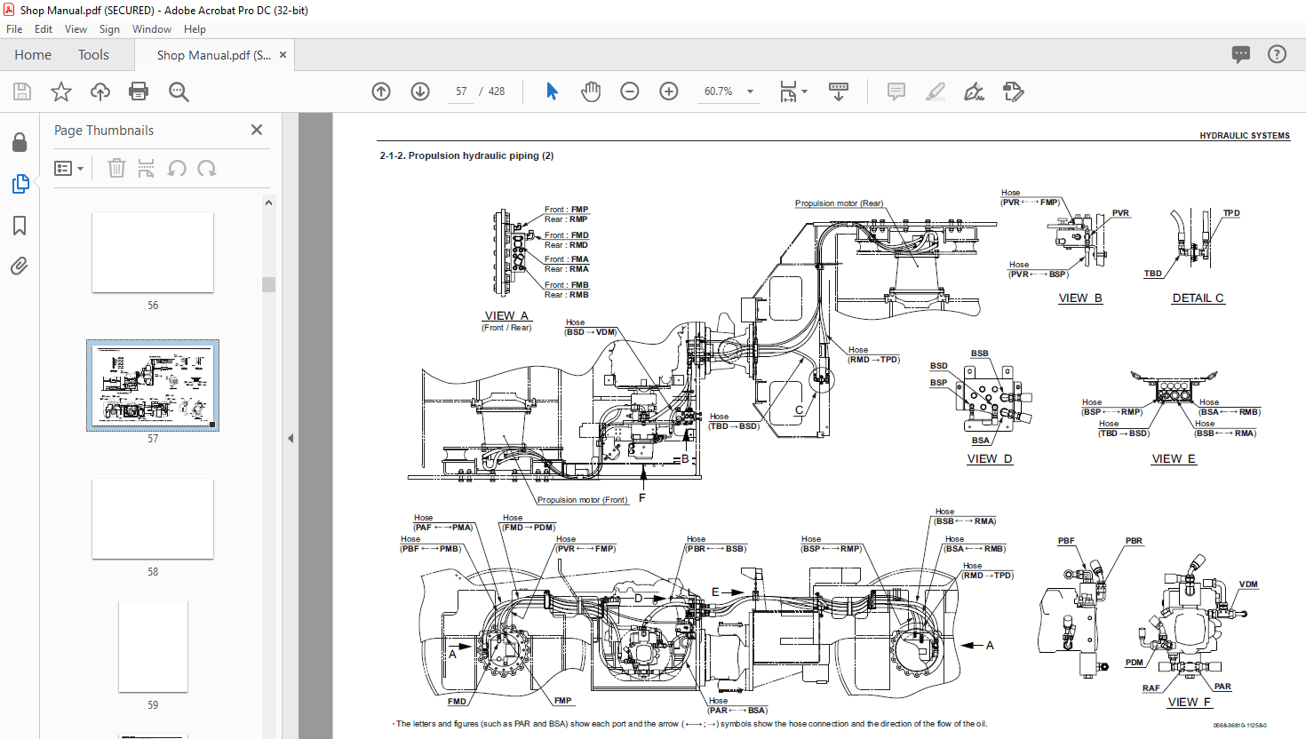
2-1-2. Propulsion hydraulic piping (2) 4-005
2-2. Hydraulic Component Specifications 4-006
2-2-1. Hydraulic pump assembly (propulsion + vibrator) 4-006
2-2-2. Propulsion hydraulic motor (front) 4-008
2-2-3. Propulsion hydraulic motor (rear) 4-010
2-2-4. Valve block 4-012
3. VIBRATOR HYDRAULIC SYSTEM
3-1. Vibrator Hydraulic Piping 4-013
3-1-1. Vibrator hydraulic piping (1) 4-013
3-1-2. Vibrator hydraulic piping (2) 4-014
3-1-3. Vibrator hydraulic piping (3) 4-015
3-2. Hydraulic Component Specifications 4-016
3-2-1. Vibrator hydraulic motor 4-016
3-2-2. Vibrator valve block 4-017
4. STEERING SYSTEM
4-1. Steering Hydraulic Piping 4-019
4-2. Steering Wheel 4-020
4-3. Hydraulic Component Specifications 4-021
4-3-1. Orbitrol 4-021
4-3-2. Steering • charge pump 4-022
SW880-1/990-1 ○0
0-003
5. ELECTRICAL SYSTEM
1. Precautions for wor k
1-1. Wire Numbers, Wire Sizes, Wire Colors and Connectors Shown in
Electrical Circuit Diagram, Wiring Harness Layout and Wiring Harnesses 5-001
1-2. Electrical Equipment Installation 5-002
2. SYSTEM CIRCUIT DIAGRAM
2-1. Electrical Circuit Diagram 5-003
3. ELECTRICAL COMPONENTS
3-1. Battery Layout 5-004
3-2. Wiring Harness Layout (1) 5-005
3-3. Wiring Harness Layout (2) 5-006
3-4. Wiring Harness Layout (3) 5-007
4. WIRING HARNESSES
4-1. Main Harness (1) 5-008
4-1. Main Harness (2) 5-010
4-2. Fuse • Relay Harness 5-012
4-3. Engine Harness 5-014
4-4. Battery Harness 5-016
4-5. Front Frame Harness 5-018
4-6. F-R Lever Harness 5-020
4-7. Panel Harness (L) 5-022
4-8. Panel Harness (R) 5-024
4-9. Floor Bord Harness 5-026
4-10. Starter Relay Harness 5-028
4-11. Torque Control Box Harness 5-029
4-12. Water Spray Pump (R) Harness 5-030
5. ELECTRICAL COMPONENT SPECIFICATIONS
5-1. Potentiometer 5-031
5-2. Exact Meter 5-032
5-3. Resistor Unit 5-033
5-4. Lever Switch 5-034
5-5. Fuse Box 5-035
5-6. Combination Meter 5-036
SW880-1/990-1 ○0
0-004
6. VIBRATORY DRUM
1. PRECAUTIONS FOR DISASSEMBLY AND REASSEMBLY 6-001
2. REMOVAL AND INSTALLATION OF VIBRATORY DRUM
2-1. Removal of Vibratory Drum 6-003
2-2. Installation of Vibratory Drum 6-008
3. VIBRATORY DRUM ASSEMBLY
3-1. Vibratory Drum Assembly 6-009
4. DISASSEMBLY AND REASSEMBLY OF VIBRATORY DRUM
4-1. Disassembly of Vibratory Drum 6-010
4-2. Reassembly of Vibratory Drum 6-023
7. BRAKE
1. BRAKE PEDAL 7-001
2. BRAKE SYSTEM 7-002
8. OPERATOR STATION
1. FLOORBOARD
1-1. Structure of Operator Station 8-001
1-2. Adjustment of Swivel Lock Release Pedal 8-002
9. WATER SPRAY SYSTEM
1. WATER SPRAY PIPING 9-001
10. INSPECTION AND ADJUSTMENT
1. INSPECTION AND ADJUSTMENT
1-1. Safety Precautions for Inspection and Adjustment 10-001
1-2. Preparation for Inspection and Adjustment 10-001
1-3. Precautions for Inspection and Adjustment 10-001
1-4. Warm-up 10-001
1-5. Inspection and Adjustment of Engine Related Items 10-001
2. MEASUREMENT AND ADJUSTMENT OF
PROPULSION CIRCUIT PRESSURE
2-1. Measurement 10-002
2-2. Adjustment 10-003
2-2-1. If pressures on both forward and reverse sides deviate from
maximum circuit pressure range by same value 10-003
2-2-2. If pressure on either the forward or reverse side deviates from
maximum circuit pressure range 10-004
SW880-1/990-1 ○0
0-005
3. MEASUREMENT AND ADJUSTMENT OF
PROPULSION CHARGE CIRCUIT PRESSURE
3-1. Measurement 10-005
3-2. Adjustment 10-006
4. MEASUREMENT OF PROPULSION SERVO CIRCUIT PRESSURE
4-1. Measurement 10-007
5. MEASUREMENT OF PARKING BRAKE RELEASE PRESSURE
5-1. Measurement 10-008
6. MEASUREMENT AND INSPECTION OF VIBRATOR CIRCUIT PRESSURE
6-1. Measurement 10-009
6-2. Inspection 10-010
6-2-1. Inspection of high pressure relief valves installed in vibrator pump 10-010
6-2-2. Inspection of high pressure relief valves (port relief valves) installed in
vibrator valve blocks in vibrator circuit 10-011
7. MEASUREMENT AND INSPECTION OF
VIBRATOR CHARGE CIRCUIT PRESSURE
7-1. Measurement 10-012
7-2. Inspection 10-013
8. MEASUREMENT AND INSPECTION OF STEERING CIRCUIT PRESSURE
8-1. Measurement 10-014
8-2. Inspection 10-015
9. MEASUREMENT OF HYDRAULIC PUMP CASE PRESSURE
9-1. Measurement of Propulsion Pump Case Pressure 10-016
9-2. Measurement of Vibrator Pump Case Pressure 10-017
10. MEASUREMENT OF PROPULSION MOTOR CASE PRESSURE
10-1. Measurement 10-018
11. MEASUREMENT OF VIBRATOR MOTOR CASE PRESSURE
11-1. Measurement 10-019
12. ADJUSTMENT OF F-R LEVER POTENTIOMETER
12-1. Adjustment of F-R Lever Operating Force 10-020
12-1-1. Adjustment of disc spring tension 10-020
12-1-2. Adjustment of steel ball thrust 10-021
12-2. Adjustment of Potentiometer 10-022
12-2-1. Adjustment of potentiometer 1 voltage when F-R lever is in “N” 10-022
12-2-2. Adjustment of potentiometer 1 voltage when forward switch operates 10-023
12-2-3. Adjustment of potentiometer 1 voltage when reverse switch operates 10-024
SW880-1/990-1 ○0
0-006
11. TROUBLESHOOTING
1. TROUBLESHOOTING
1-1. Safety Precautions for Troubleshooting 11-001
1-2. Important Information for Troubleshooting 11-001
1-3. Before Starting 11-002
1-4. Wire Number and Color Code 11-002
2. ELECTRICAL SYSTEM TROUBLESHOOTING
2-1. When Performing Electrical System Fault Diagnosis 11-003
2-1-1. Precautions to take during electrical circuit fault diagnosis 11-003
2-1-2. Inspection procedures using a tester 11-004
2-1-3. Inspection of electrical system 11-009
2-2. Fault Codes 11-011
2-2-1. Fault detection 11-011
2-2-2. Fault lamps 11-011
2-2-3. Flash out of fault codes 11-012
2-2-4. Fault code list 11-013
2-3. Error Codes 11-022
2-3-1. Description of error codes 11-022
2-3-2. Error code list 11-023
2-4. Engine 11-025
2-4-1. Engine will not start (Starter motor does not run) 1/17 11-025
2-4-1. Engine will not start (Starter motor does not run) 2/17 11-027
2-4-1. Engine will not start (Starter motor does not run) 3/17 11-029
2-4-1. Engine will not start (Starter motor does not run) 4/17 11-031
2-4-1. Engine will not start (Starter motor does not run) 5/17 11-033
2-4-1. Engine will not start (Starter motor does not run) 6/17 11-035
2-4-1. Engine will not start (Starter motor does not run) 7/17 11-037
2-4-1. Engine will not start (Starter motor does not run) 8/17 11-039
2-4-1. Engine will not start (Starter motor does not run) 9/17 11-041
2-4-1. Engine will not start (Starter motor does not run) 10/17 11-043
2-4-1. Engine will not start (Starter motor does not run) 11/17 11-045
2-4-1. Engine will not start (Starter motor does not run) 12/17 11-047
2-4-1. Engine will not start (Starter motor does not run) 13/17 11-049
2-4-1. Engine will not start (Starter motor does not run) 14/17 11-051
2-4-1. Engine will not start (Starter motor does not run) 15/17 11-053
2-4-1. Engine will not start (Starter motor does not run) 16/17 11-055
2-4-1. Engine will not start (Starter motor does not run) 17/17 11-057
2-4-2. Engine will not start (But starter motor runs) 11-059
SW880-1/990-1 ○0
0-007
2-4-3. No charging 11-061
2-4-4. Grid heater does not work
(Engine starting performance is bad in cold weather) 11-061
2-4-5. Starter motor runs even when F-R lever is not at “N” and
parking brake is not applied 11-063
2-4-6. Engine speed cannot be switched 11-063
2-5. Propulsion 11-065
2-5-1. Machine and engine suddenly stops 1/11 11-065
2-5-1. Machine and engine suddenly stops 2/11 11-067
2-5-1. Machine and engine suddenly stops 3/11 11-069
2-5-1. Machine and engine suddenly stops 4/11 11-071
2-5-1. Machine and engine suddenly stops 5/11 11-073
2-5-1. Machine and engine suddenly stops 6/11 11-075
2-5-1. Machine and engine suddenly stops 7/11 11-077
2-5-1. Machine and engine suddenly stops 8/11 11-079
2-5-1. Machine and engine suddenly stops 9/11 11-081
2-5-1. Machine and engine suddenly stops 10/11 11-083
2-5-1. Machine and engine suddenly stops 11/11 11-085
2-5-2. Machine and engine suddenly stops in automatic speed mode 1/2 11-087
2-5-2. Machine and engine suddenly stops in automatic speed mode 2/2 11-089
2-5-3. Machine moves neither forward nor backward 1/6 11-091
2-5-3. Machine moves neither forward nor backward 2/6 11-093
2-5-3. Machine moves neither forward nor backward 3/6 11-095
2-5-3. Machine moves neither forward nor backward 4/6 11-097
2-5-3. Machine moves neither forward nor backward 5/6 11-099
2-5-3. Machine moves neither forward nor backward 6/6 11-101
2-5-4. Machine speed cannot be changed 11-103
2-5-5. Auto speed function does not work 1/9 11-105
2-5-5. Auto speed function does not work 2/9 11-107
2-5-5. Auto speed function does not work 3/9 11-109
2-5-5. Auto speed function does not work 4/9 11-111
2-5-5. Auto speed function does not work 5/9 11-113
2-5-5. Auto speed function does not work 6/9 11-115
2-5-5. Auto speed function does not work 7/9 11-117
2-5-5. Auto speed function does not work 8/9 11-119
2-5-5. Auto speed function does not work 9/9 11-121
2-5-6. Brake cannot be released 11-123
2-5-7. Brake does not work 11-125
2-5-8. Emergency exit propulsion switch does not work 11-127
SW880-1/990-1 ○0
0-008
2-6. Vibration 11-129
2-6-1. No vibration occurs 1/3 11-129
2-6-1. No vibration occurs 2/3 11-131
2-6-1. No vibration occurs 3/3 11-133
2-6-2. Vibration frequency cannot be switched 1/3 11-135
2-6-2. Vibration frequency cannot be switched 2/3 11-137
2-6-2. Vibration frequency cannot be switched 3/3 11-139
2-6-3. Continuous/automatic vibration mode cannot be switched 1/2 11-141
2-6-3. Continuous/automatic vibration mode cannot be switched 2/2 11-143
2-6-4. Front and rear vibratory drums cannot perform one-drum vibration 11-145
2-7. Exact Meter 11-147
2-7-1. Exact meter indicator lamp does not illuminate while driving 1/9 11-147
2-7-1. Exact meter indicator lamp does not illuminate while driving 2/9 11-149
2-7-1. Exact meter indicator lamp does not illuminate while driving 3/9 11-151
2-7-1. Exact meter indicator lamp does not illuminate while driving 4/9 11-153
2-7-1. Exact meter indicator lamp does not illuminate while driving 5/9 11-155
2-7-1. Exact meter indicator lamp does not illuminate while driving 6/9 11-157
2-7-1. Exact meter indicator lamp does not illuminate while driving 7/9 11-159
2-7-1. Exact meter indicator lamp does not illuminate while driving 8/9 11-161
2-7-1. Exact meter indicator lamp does not illuminate while driving 9/9 11-163
2-7-2. No vehicle speed indication on display 1/3 11-165
2-7-2. No vehicle speed indication on display 2/3 11-167
2-7-2. No vehicle speed indication on display 3/3 11-169
2-8. Water Spray 11-171
2-8-1. Continuous water spray does not operate 1/4 11-171
2-8-1. Continuous water spray does not operate 2/4 11-173
2-8-1. Continuous water spray does not operate 3/4 11-175
2-8-1. Continuous water spray does not operate 4/4 11-177
2-8-2. Continuous water spray works, but intermittent water spray
does not operate 1/2 11-179
2-8-2. Continuous water spray works, but intermittent water spray
does not operate 2/2 11-181
2-8-3. Continuous water spray works, but automatic water spray
does not operate 11-183
2-9. Lighting 11-185
2-9-1. Head lamp and flood lamp do not light 11-185
2-9-2. Combination meter warning lamp or indicator lamp is abnormal 11-187
2-9-3. Tachometer reading is abnormal 11-189
2-9-4. Hour meter is abnormal 11-189
SW880-1/990-1 ○0
0-009
2-9-5. Temperature meter is abnormal 11-191
2-9-6. Fuel meter is abnormal 11-191
2-9-7. Hydraulic oil filter warning lamp remains ON 11-193
2-9-8. Engine oil pressure warning lamp remains ON 11-195
2-9-9. Charge warning lamp remains ON 11-197
2-9-10. Vibration indicator lamp does not light 11-199
2-9-11. Water spray indicator lamp does not light 11-201
2-9-12. Parking brake indicator lamp does not light 11-203
2-9-13. Horn does not sound 11-205
2-7-14. Backup buzzer does not sound 11-205
3. HYDRAULIC SYSTEM TROUBLESHOOTING
3-1. When Performing Hydraulic System Troubleshooting 11-206
3-2. Propulsion System 11-207
3-2-1. Machine moves neither forward nor backward 1/2 11-207
3-2-1. Machine moves neither forward nor backward 2/2 11-208
3-2-2. Machine moves in one direction only (forward or backward) 11-208
3-2-3. Slow machine speed or small drive force 1/2 11-208
3-2-3. Slow machine speed or small drive force 2/2 11-209
3-2-4. Machine does not stop completely with F-R lever in “N” 11-209
3-2-5. Propulsion system is overheating 11-210
3-2-6. Abnormal noise from propulsion system 11-210
3-3. Vibrator System 11-211
3-3-1. No vibration 11-211
3-3-2. Only front or rear vibratory drum can vibrate
(two-drum vibration cannot be performed) 11-212
3-3-3. Vibrator frequency is too low 11-212
3-3-4. Amplitude does not switch between high and low 11-213
3-3-5. Vibrator does not stop 11-213
3-3-6. Vibrator system is overheating 11-213
3-3-7. Abnormal noise from vibrator system 11-214
3-4. Steering System 11-215
3-4-1. Steering wheel is hard to turn 11-215
3-4-2. Steering response is slow 11-215
3-4-3. Steering wheel backlash or play is large 11-216
3-4-4. Steering system is overheating 11-216
3-4-5. Abnormal noise from steering system 11-216
IMAGES PREVIEW OF THE MANUAL:
More products