$35
Sakai SW880990 SHOP MANUAL 3498-65684-0 - PDF DOWNLOAD
Sakai SW880/990 Shop Manual 3498-65684-0 – PDF DOWNLOAD
FILE DETAILS:
Sakai SW880/990 Shop Manual 3498-65684-0 – PDF DOWNLOAD
Language : English
Pages :354
Downloadable : Yes
File Type : PDF
TABLE OF CONTENTS:
Sakai SW880/990 Shop Manual 3498-65684-0 – PDF DOWNLOAD
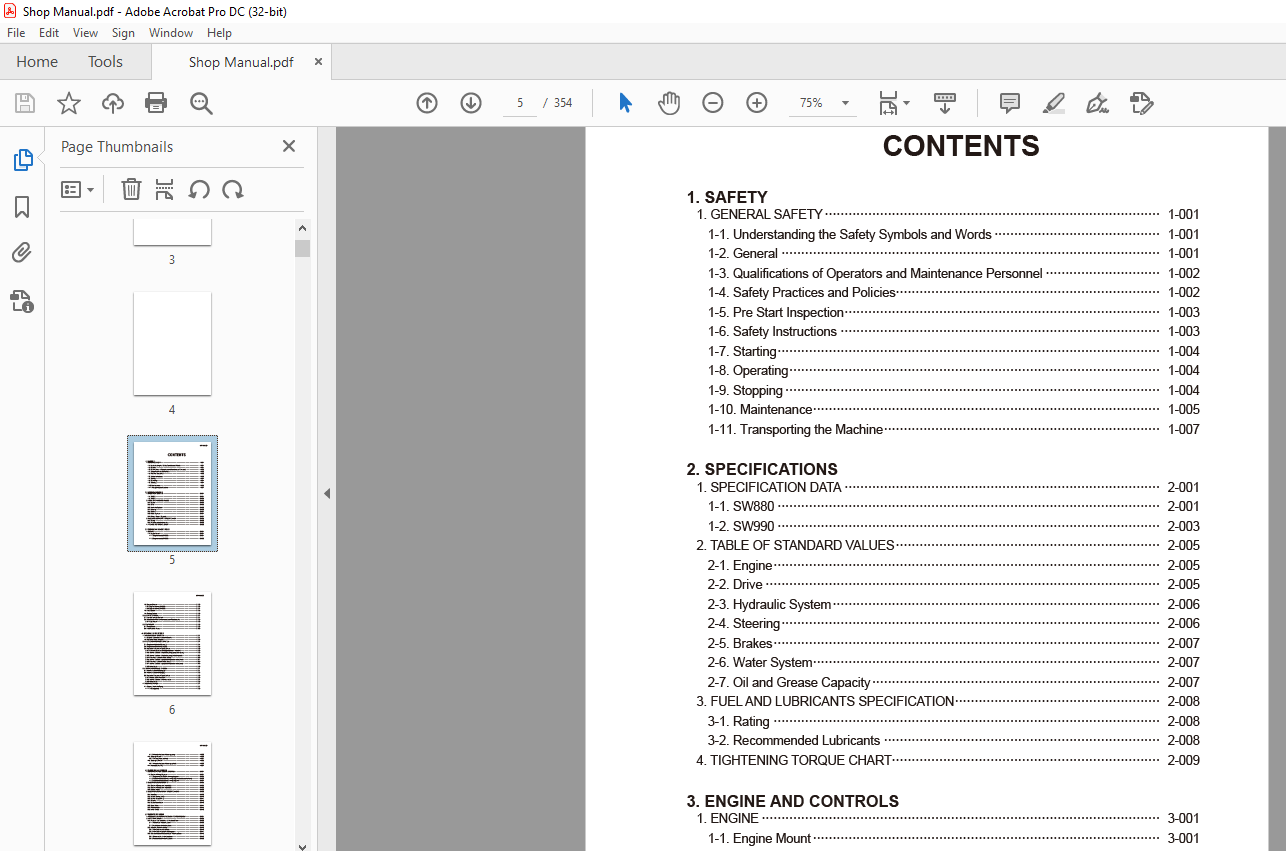
1. SAFETY
1. GENERAL SAFETY 1-001
1-1. Understanding the Safety Symbols and Words 1-001
1-2. General 1-001
1-3. Qualifications of Operators and Maintenance Personnel 1-002
1-4. Safety Practices and Policies 1-002
1-5. Pre Start Inspection 1-003
1-6. Safety Instructions 1-003
1-7. Starting 1-004
1-8. Operating 1-004
1-9. Stopping 1-004
1-10. Maintenance 1-005
1-11. Transporting the Machine 1-007
2. SPECIFICATIONS
1. SPECIFICATION DATA 2-001
1-1. SW880 2-001
1-2. SW990 2-003
2. TABLE OF STANDARD VALUES 2-005
2-1. Engine 2-005
2-2. Drive 2-005
2-3. Hydraulic System 2-006
2-4. Steering 2-006
2-5. Brakes 2-007
2-6. Water System 2-007
2-7. Oil and Grease Capacity 2-007
3. FUEL AND LUBRICANTS SPECIFICATION 2-008
3-1. Rating 2-008
3-2. Recommended Lubricants 2-008
4. TIGHTENING TORQUE CHART 2-009
3. ENGINE AND CONTROLS
1. ENGINE 3-001
1-1. Engine Mount 3-001
1-1-1. Engine mount (SW880) 3-001
1-1-2. Engine mount (SW990) 3-002
SW880/990○0
1-2. Engine Exterior 3-003
1-2-1. Engine exterior (SW880) 3-003
1-2-2. Engine exterior (SW990) 3-004
1-3. Fuel System 3-005
1-4. Cooling System 3-006
2. CONTROL SYSTEM 3-007
2-1. Forward-reverse Control 3-007
2-2. Adjustment of Forward-reverse Lever Potentiometer 3-008
2-2-1. Adjustment 3-008
3. PUMP MOUNT 3-009
3-1. Pump Mount 3-009
3-2. Installation of Pump 3-010
4. HYDRAULIC SYSTEMS
1. SYSTEM CIRCUIT DIAGRAM 4-001
1-1. Graphic Symbols for Hydraulic Circuits 4-001
1-2. Hydraulic Circuit Diagram 4-003
2. PROPULSION HYDRAULIC SYSTEM 4-004
2-1. Propulsion Hydraulic Piping (1) 4-004
2-2. Propulsion Hydraulic Piping (2) 4-005
2-3. Hydraulic Component Specifications 4-006
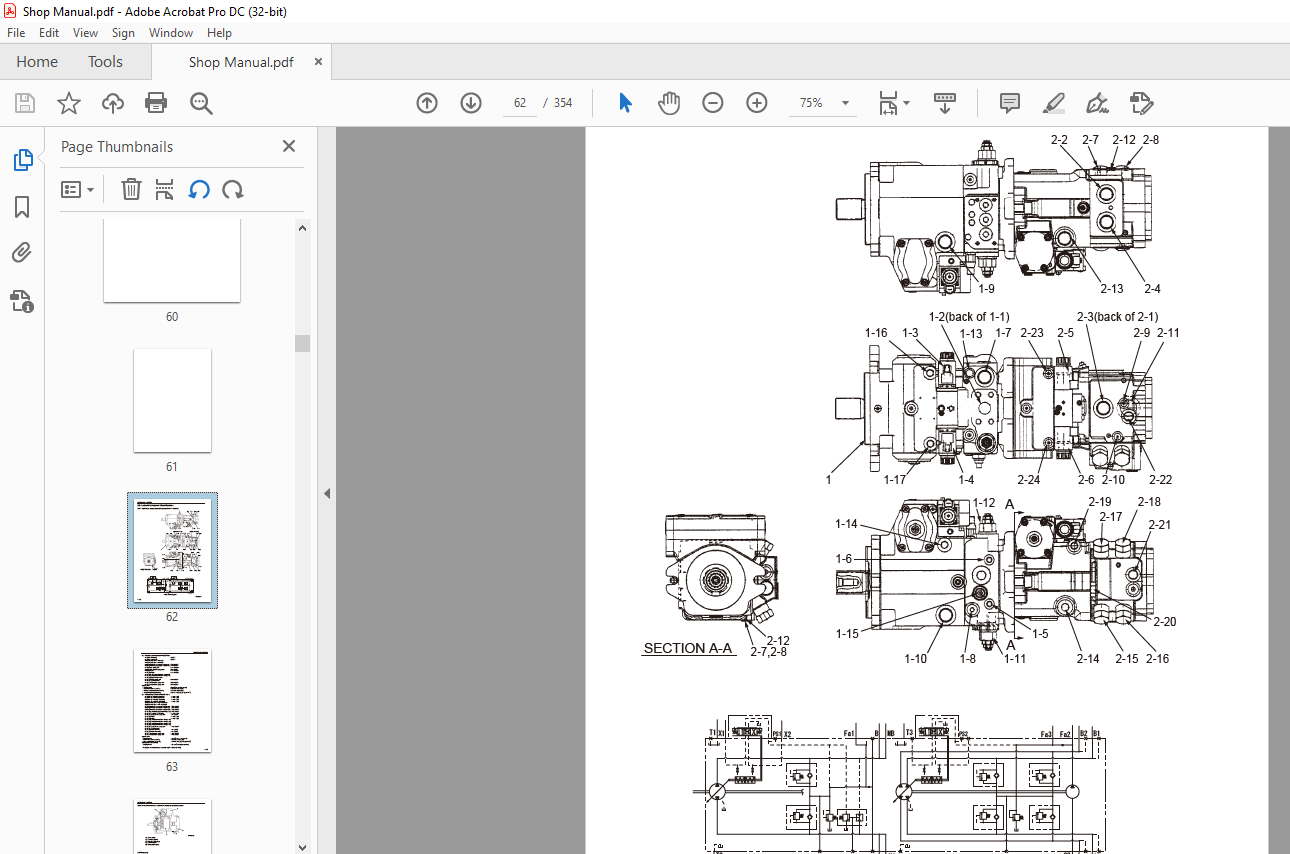
2-3-1. Hydraulic pump assembly (propulsion + vibrator) 4-006
2-3-2. Internal structure of hydraulic pump (propulsion pump) 4-008
2-3-3. Internal structure of hydraulic pump (vibrator pump) 4-012
2-3-4. Propulsion hydraulic motor (front) 4-016
2-3-5. Internal structure of propulsion hydraulic motor (front) 4-017
2-3-6. Propulsion hydraulic motor (rear) 4-018
2-3-7. Internal structure of propulsion hydraulic motor (rear) 4-019
2-3-8. Valve block 4-020
3. VIBRATOR HYDRAULIC SYSTEM 4-021
3-1. Vibrator Hydraulic Piping (1) 4-021
3-2. Vibrator Hydraulic Piping (2) 4-022
3-3. Hydraulic Component Specifications 4-023
3-3-1. Vibrator hydraulic motor 4-023
3-3-2. Internal structure of vibrator motor 4-024
3-3-3. Valve block 4-025
4. STEERING SYSTEM 4-027
4-1. Steering Hydraulic Piping 4-027
4-1-1. Steering pump 4-028
SW880/990○0
4-1-2. Internal structure of steering pump 4-029
4-2. Steering Wheel 4-030
4-2-1. Steering valve (orbitrol) 4-031
4-3. Steering Cylinder 4-032
4-3-1. Internal structure of steering cylinder 4-033
4-4. Frame (Center Pin) 4-034
5. ELECTRICAL SYSTEM
1. GENERAL SYSTEM CIRCUIT DIAGRAM 5-001
1-1. Electrical Wiring Diagram 5-001
1-1-1. Engine-related electrical wiring diagram 5-002
1-1-2. Vehicle-related electrical wiring diagram (vehicle control unit) 5-003
1-1-3. Vehicle-related electrical wiring diagram 5-004
2. ELECTRICAL COMPONENTS 5-005
2-1. Electrical Component Layout (1) 5-005
2-2. Electrical Component Layout (2) 5-006
2-3. Battery Layout 5-008
3. ELECTRICAL COMPONENT SPECIFICATIONS 5-009
3-1. Fuse Box 5-009
3-2. Vehicle Control (V/C) 5-010
3-3. Control Box (EMR 3) 5-011
3-4. Resistor 5-012
3-5. Combination Meter 5-013
3-6. Exact Meter 5-014
3-7. Potentiometer 5-015
3-8. Lever Switch 5-016
6. VIBRATORY DRUM
1. PRECAUTIONS FOR DISASSEMBLY AND REASSEMBLY 6-001
2. VIBRATORY DRUM 6-003
2-1. Removal and Installation of Vibratory Drum 6-003
2-1-1. Removal of vibratory drum 6-003
2-1-2. Installation of vibratory drum 6-009
2-2. Vibratory Drum Assembly 6-010
2-2-1. Vibratory drum assembly 6-010
2-2-2. Vibratory drum exploded diagram 6-011
2-3. Disassembly and Reassembly of Vibratory Drum 6-012
2-3-1. Disassembly of vibratory drum 6-012
2-3-2. Reassembly of vibratory drum 6-026
SW880/990○0
7. BRAKES
1. BRAKE SYSTEM 7-001
1-1. Brake Pedal 7-001
1-2. Brake Circuit Configuration 7-002
8. OPERATOR STATION
1. FLOORBOARD 8-001
1-1. Operator Station 8-001
1-2. Structure of Operator Station 8-002
1-3. Adjustment of Swivel Lock Release Pedal 8-003
9. WATER SPRAY SYSTEM
1. WATER SPRAY SYSTEM 9-001
1-1. Water Spray System 9-001
1-2. Water Spray Pump 9-002
10. INSPECTION AND ADJUSTMENT
1. INSPECTION AND ADJUSTMENT 10-001
1-1. Inspection and Adjustment 10-001
1-1-1. Safety precautions for inspection and adjustment 10-001
1-1-2. Preparation for inspection and adjustment 10-002
1-1-3. Precautions for inspection and adjustment 10-002
1-1-4. Warm-up 10-002
2. MEASUREMENT AND ADJUSTMENT OF PROPULSION CIRCUIT
PRESSURE 10-003
2-1. Measurement 10-003
2-2. Adjustment 10-004
2-2-1. If the pressures on both the forward and reverse sides deviate
from the maximum circuit pressure range by the same value 10-004
2-2-2. If the pressure on either the forward or reverse side deviates
from the maximum circuit pressure range 10-005
3. MEASUREMENT AND ADJUSTMENT OF PROPULSION CHARGE
CIRCUIT PRESSURE 10-006
3-1. Measurement 10-006
3-2. Adjustment 10-007
4. MEASUREMENT OF PROPULSION SERVO CIRCUIT PRESSURE 10-008
4-1. Measurement 10-008
5. MEASUREMENT OF PARKING BRAKE RELEASE PRESSURE 10-009
5-1. Measurement 10-009
SW880/990○0
6. MEASUREMENT AND INSPECTION OF VIBRATOR CIRCUIT PRESSURE 10-010
6-1. Measurement 10-010
6-2. Inspection 10-011
6-2-1. Inspection of the high-pressure relief valves installed in the
vibrator pump 10-011
6-2-2. Inspection of the high-pressure relief valves (port relief valves)
installed in the valve blocks in the vibrator circuit 10-012
7. MEASUREMENT AND INSPECTION OF VIBRATION CHARGE
CIRCUIT PRESSURE 10-013
7-1. Measurement 10-013
7-2. Inspection 10-014
8. MEASUREMENT AND INSPECTION OF STEERING CIRCUIT PRESSURE 10-015
8-1. Measurement 10-015
8-2. Inspection 10-016
11. TROUBLESHOOTING
1. TROUBLESHOOTING 11-001
1-1. Safety Precautions for Troubleshooting 11-001
1-2. Important Information for Troubleshooting 11-002
1-3. Before Starting 11-002
1-4. Wire Color Code and Number 11-002
2. ELECTRICAL SYSTEM TROUBLESHOOTING 11-003
2-1. When Performing Electrical System Fault Diagnosis 11-003
2-1-1. Safety rules and precautions to take during electric circuit fault
diagnosis 11-003
2-1-2. Inspection procedures using a tester 11-004
2-1-3. Inspection of electrical system 11-008
2-2. Blink Codes 11-010
2-2-1. Description of blink codes 11-010
2-2-2. Blink code list 11-011
2-3. Error Codes 11-015
2-3-1. Description of error codes 11-015
2-3-2. Error code list 11-015
2-4. Engine 11-017
2-4-1. Engine will not start (1/8) 11-017
2-4-1. Engine will not start (2/8) 11-019
2-4-1. Engine will not start (3/8) 11-021
2-4-1. Engine will not start (4/8) 11-023
2-4-1. Engine will not start (5/8) 11-025
SW880/990○0
2-4-1. Engine will not start (6/8) 11-027
2-4-1. Engine will not start (7/8) 11-029
2-4-1. Engine will not start (8/8) 11-031
2-4-2. Insufficient output of engine or engine malfunction (1/2) 11-033
2-4-2. Insufficient output of engine or engine malfunction (2/2) 11-035
2-4-3. No charging 11-037
2-4-4. Engine speed cannot be switched 11-039
2-4-5. Glow plug is not heated (Engine starting performance is bad) 11-041
2-4-6. Engine check lamp does not illuminate 11-043
2-4-7. CAN communication is abnormal 11-045
2-5. Propulsion 11-047
2-5-1. Vehicle moves neither forward nor backward (1/5) 11-047
2-5-1. Vehicle moves neither forward nor backward (2/5) 11-049
2-5-1. Vehicle moves neither forward nor backward (3/5) 11-051
2-5-1. Vehicle moves neither forward nor backward (4/5) 11-053
2-5-1. Vehicle moves neither forward nor backward (5/5) 11-055
2-5-2. Vehicle moves neither forward nor backward only in
automatic speed mode 11-057
2-5-3. Vehicle speed cannot be changed 11-059
2-5-4. Automatic speed function does not work (1/7) 11-061
2-5-4. Automatic speed function does not work (2/7) 11-063
2-5-4. Automatic speed function does not work (3/7) 11-065
2-5-4. Automatic speed function does not work (4/7) 11-067
2-5-4. Automatic speed function does not work (5/7) 11-069
2-5-4. Automatic speed function does not work (6/7) 11-071
2-5-4. Automatic speed function does not work (7/7) 11-073
2-5-5. Brake cannot be released 11-075
2-5-6. Brake does not operate 11-077
2-5-7. Emergency exit propulsion cannot be performed 11-079
2-6. Vibration 11-081
2-6-1. No vibration occurs (1/2) 11-081
2-6-1. No vibration occurs (2/2) 11-083
2-6-2. Vibration frequency cannot be switched (1/2) 11-085
2-6-2. Vibration frequency cannot be switched (2/2) 11-087
2-6-3. High/low-vibration cannot be switched 11-089
2-6-4. Continuous/automatic-vibration mode cannot be switched 11-091
2-6-5. Front and rear vibratory drums cannot perform one-drum vibration 11-093
2-7. Exact Meter 11-095
2-7-1. Exact meter indicator lamp does not illuminate (during driving) (1/2) 11-095
SW880/990○0
2-7-1. Exact meter indicator lamp does not illuminate (during driving) (2/2) 11-097
2-7-2. No vehicle speed indication on the display 11-099
2-8. Water Spray 11-101
2-8-1. Continuous water spray cannot be performed (1/4) 11-101
2-8-1. Continuous water spray cannot be performed (2/4) 11-103
2-8-1. Continuous water spray cannot be performed (3/4) 11-105
2-8-1. Continuous water spray cannot be performed (4/4) 11-107
2-8-2. Continuous water spray works, but intermittent water spray
cannot be performed 11-109
2-8-3. Continuous water spray works, but automatic water spray
cannot be performed 11-111
2-9. Lighting 11-113
2-9-1. Headlamps and working lamps do not light 11-113
2-9-2. Illumination of combination meter does not turn on 11-115
2-9-3. Combination meter warning lamp or indicator lamp is abnormal 11-115
2-9-4. Tachometer reading is abnormal (1/2) 11-117
2-9-4. Tachometer reading is abnormal (2/2) 11-119
2-9-5. Hour meter is abnormal 11-119
2-9-6. Temperature gauge is abnormal 11-121
2-9-7. Fuel gauge is abnormal 11-123
2-9-8. Hydraulic oil filter warning lamp remains ON 11-123
2-9-9. Oil pressure warning lamp remains ON 11-125
2-9-10. Charge warning lamp remains ON 11-127
2-9-11. Vibration indicator lamp does not light 11-127
2-9-12. Water spray indicator lamp does not light 11-129
2-9-13. Working lamp indicator lamp does not light 11-131
2-9-14. Parking brake indicator lamp does not light 11-131
2-9-15. Horn does not sound 11-133
2-9-16. Back buzzer does not sound 11-133
3. HYDRAULIC SYSTEM TROUBLESHOOTING 11-134
3-1. When Performing Hydraulic System Troubleshooting 11-134
3-2. Propulsion 11-135
3-2-1. Vehicle moves neither forward nor backward (1/2) 11-135
3-2-1. Vehicle moves neither forward nor backward (2/2) 11-136
3-2-2. Vehicle moves in one direction only (forward or backward) 11-136
3-2-3. Slow vehicle speed or small drive force 11-136
3-2-4. Vehicle does not stop completely with forward/reverse lever in
neutral position 11-137
3-2-5. Propulsion system is overheating 11-137
SW880/990○0
3-2-6. Abnormal noise from propulsion system 11-137
3-3. Vibrator System 11-138
3-3-1. No vibration 11-138
3-3-2. Only front or rear vibratory drum can vibrate (two-drum vibration
cannot be performed) 11-139
3-3-3. Vibrator frequency is too low 11-139
3-3-4. Amplitude cannot be switched between high and low 11-139
3-3-5. Vibrator does not stop 11-140
3-3-6. Vibrator system is overheating 11-140
3-3-7. Abnormal noise from vibrator system 11-140
3-4. Steering 11-141
3-4-1. Steering wheel is hard to turn 11-141
3-4-2. Steering response is slow 11-141
3-4-3. Steering wheel backlash or play is large 11-142
3-4-4. Steering system is overheating 11-142
3-4-5. Abnormal noise from steering system 11-142
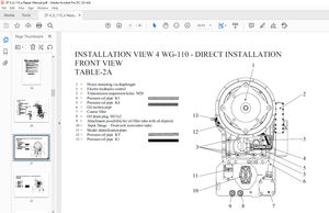
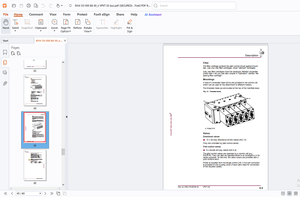
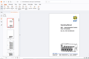
IMAGES PREVIEW OF THE MANUAL:
More products