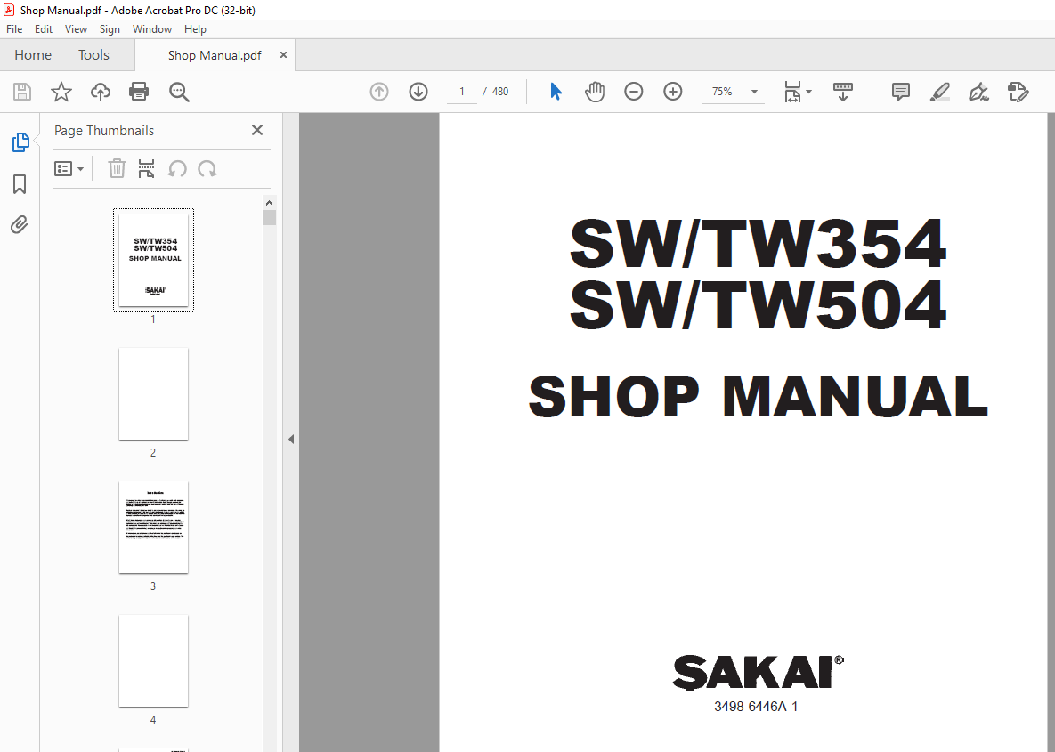
$39
Sakai SWTW354 SWTW504 Shop Manual 3498-6446A-1 - PDF DOWNLOAD
Sakai SW/TW354 SW/TW504 Shop Manual 3498-6446A-1 – PDF DOWNLOAD
FILE DETAILS:
Sakai SW/TW354 SW/TW504 Shop Manual 3498-6446A-1 – PDF DOWNLOAD
Language : English
Pages :480
Downloadable : Yes
File Type : PDF
TABLE OF CONTENTS:
Sakai SW/TW354 SW/TW504 Shop Manual 3498-6446A-1 – PDF DOWNLOAD
1. SAFETY
1. GENERAL SAFETY
1-1. Understanding the Safety Symbols and Words 1-001
1-2. General 1-001
1-3. Qualifications of Operators and Maintenance Personnel 1-002
1-4. Safety Practices and Policies 1-002
1-5. Pre Start Inspection 1-003
1-6. Safety Instructions 1-003
1-7. Starting 1-004
1-8. Operating 1-004
1-9. Stopping 1-004
1-10. Maintenance 1-005
1-11. Transporting the Machine 1-007
2. SPECIFICATIONS
1. SPECIFICATION DATA
1-1. SW354 2-001
1-2. SW354 ROPS 2-003
1-3. TW354 2-005
1-4. TW354 ROPS 2-007
1-5. TW504 2-009
1-6. TW504 ROPS 2-011
1-7. Common Specifications 2-013
2. TABLE OF STANDARD VALUES
2-1. Engine 2-014
2-2. Propulsion 2-014
2-3. Hydraulic System 2-015
2-4. Steering 2-015
2-5. Brakes 2-016
2-6. Capacities 2-016
3. FUEL AND LUBRICANTS SPECIFICATION
3-1. Rating 2-017
3-2. Recommended Lubricants 2-017
4. TIGHTENING TORQUE CHART 2-018
○1
SW/TW354,SW/TW504 ○1
0-002
5. SPECIFICATION DATA (SW504)
5-1. SW504 2-019
5-2. SW504 ROPS 2-021
5-3. Common Specifications 2-023
6. TABLE OF STANDARD VALUES (SW504)
6-1. Engine 2-024
6-2. Propulsion 2-024
6-3. Hydraulic System 2-024
6-4. Steering 2-025
6-5. Brakes 2-025
6-6. Capacities 2-025
7. FUEL AND LUBRICANTS SPECIFICATION (SW504)
7-1. Rating 2-026
7-2. Recommended Lubricants 2-026
3. ENGINE AND CONTROLS
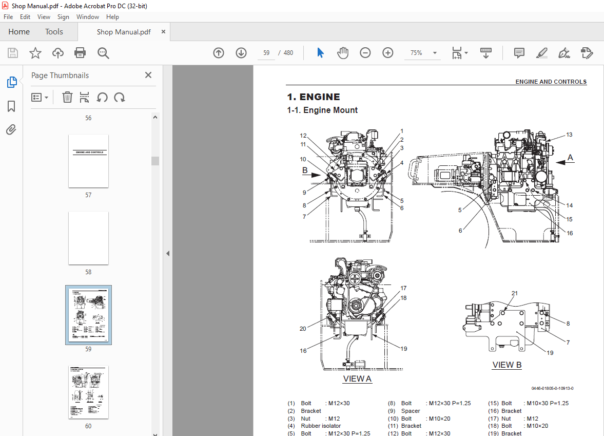
1. ENGINE
1-1. Engine Mount 3-001
2. CONTROL SYSTEM
2-1. Throttle Control 3-002
2-2. Forward-reverse Control 3-003
3. PUMP MOUNT
3-1. Pump Mount 3-004
3-1-1. Installation of pump 3-005
4. ENGINE (SW504)
4-1. Engine Mount 3-006
5. FUEL SYSTEM (SW504) 3-007
6. CONTROL SYSTEM (SW504)
6-1. Throttle Control 3-009
6-2. Forward-reverse Control 3-010
7. PUMP MOUNT (SW504)
7-1. Pump Mount 3-011
7-1-1. Installation of pump 3-012
4. HYDRAULIC SYSTEMS
1. SYSTEM CIRCUIT DIAGRAM
1-1. Graphic Symbols for Hydraulic Circuits 4-001
1-2. Hydraulic Circuit Diagram 4-003
1-2-1. Hydraulic circuit diagram (SW354) 4-003
1-2-2. Hydraulic circuit diagram (TW354) 4-004
1-2-3. Hydraulic circuit diagram (TW504) 4-005
2. PROPULSION HYDRAULIC SYSTEM
2-1. Propulsion Hydraulic Piping 4-006
2-1-1. Propulsion hydraulic piping (F) (SW/TW354) 4-006
2-1-2. Propulsion hydraulic piping (F) (TW504) 4-007
2-1-3. Propulsion hydraulic piping (R) (SW354) 4-008
2-1-4. Propulsion hydraulic piping (R) (TW354) 4-009
2-1-5. Propulsion hydraulic piping (R) (TW504) 4-010
2-2. Hydraulic Component Specifications 4-011
2-2-1. Propulsion hydraulic pump 4-011
2-2-2. Propulsion hydraulic motor (F) (SW/TW354) 4-013
2-2-3. Propulsion hydraulic motor (F) (TW504) 4-014
2-2-4. Propulsion hydraulic motor (R) (SW354) 4-015
2-2-5. Propulsion hydraulic motor (R) (TW354,504) 4-016
2-2-6. Differential lock valve (TW354,504) 4-017
3. VIBRATOR HYDRAULIC SYSTEM
3-1. Vibrator Hydraulic Piping 4-018
3-1-1. Vibrator hydraulic piping (SW354) 4-018
3-1-2. Vibrator hydraulic piping (TW354) 4-019
3-1-3. Vibrator hydraulic piping (TW504) 4-020
3-2. Hydraulic Component Specifications 4-021
3-2-1. Hydraulic pump assembly (vibrator (F) + steering • charge) 4-021
3-2-2. Vibrator hydraulic pump (R) (SW354) 4-022
3-2-3. Vibrator hydraulic motor 4-023
3-2-4. Cooling fan drive hydraulic motor 4-024
3-2-5. Vibrator solenoid valve (F), (R) (SW/TW354) 4-025
3-2-6. Vibrator solenoid valve (TW504) 4-026
4. STEERING SYSTEM
4-1. Steering Hydraulic Piping 4-027
4-1-1. Steering hydraulic piping (SW/TW354) 4-027
4-1-2. Steering hydraulic piping (TW504) 4-028
4-2. Steering Wheel 4-029
4-3. Hydraulic Component Specifications 4-030
4-3-1. Orbitrol 4-030
SW/TW354,SW/TW504 ○1
0-004
5. HYDRAULIC CIRCUIT DIAGRAM (SW504)
5-1. Hydraulic Circuit Diagram 4-031
6. PROPULSION HYDRAULIC SYSTEM (SW504)
6-1. Propulsion Hydraulic Piping 4-032
6-1-1. Propulsion hydraulic piping (F) 4-032
6-1-2. Propulsion hydraulic piping (R) 4-033
6-2. Hydraulic Component Specifications 4-034
6-2-1. Propulsion hydraulic pump 4-034
6-2-2. Propulsion hydraulic motor (R) 4-036
7. VIBRATOR HYDRAULIC SYSTEM (SW504)
7-1. Vibrator Hydraulic Piping 4-037
7-2. Hydraulic Component Specifications 4-038
7-2-1. Hydraulic pump assembly (vibrator + steering • charge) 4-038
7-2-2. Cooling fan drive hydraulic motor 4-039
7-2-3. Vibrator solenoid valve assembly 4-040
8. STEERING SYSTEM (SW504)
8-1. Steering Hydraulic Piping 4-041
8-2. Hydraulic Component Specifications 4-042
8-2-1. Orbitrol 4-042
5. ELECTRICAL SYSTEM
1. Precautions for wor k
1-1. Wire Numbers, Wire Sizes, Wire Colors and Connectors Shown in
Electrical Circuit Diagram, Wiring Harness Layout and Wiring Harnesses 5-001
2. SYSTEM CIRCUIT DIAGRAM
2-1. Electrical Circuit Diagram (SW354) 5-003
2-2. Electrical Circuit Diagram (SW354 ROPS) 5-004
2-3. Electrical Circuit Diagram (TW354) 5-005
2-4. Electrical Circuit Diagram (TW354 ROPS) 5-006
2-5. Electrical Circuit Diagram (TW504) 5-007
2-6. Electrical Circuit Diagram (TW504 ROPS) 5-008
3. ELECTRICAL COMPONENTS
3-1. Wiring Harness Layout (SW354) 5-009
3-1-1. Wiring harness layout (1) 5-009
3-1-2. Wiring harness layout (2) 5-010
3-2. Wiring Harness Layout (TW354) 5-011
3-2-1. Wiring harness layout (1) 5-011
3-2-2. Wiring harness layout (2) 5-012
○1
SW/TW354,SW/TW504 ○1
0-005
3-3. Wiring Harness Layout (TW504) 5-013
3-3-1. Wiring harness layout (1) 5-013
3-3-2. Wiring harness layout (2) 5-014
4. WIRING HARNESSES
4-1. Engine Harness 5-015
4-2. Dashboard Harness 5-017
4-3. Frame (F) Harness 5-019
4-3-1. Frame (F) harness (SW/TW354) 5-019
4-3-2. Frame (F) harness (TW504) 5-021
4-4. Frame (R) Harness 5-023
4-5. Stater Switch Harness 5-025
4-6. Control Switch Harness 5-026
4-7. Working Switch Harness 5-027
4-7-1. Working switch harness (except ROPS) 5-027
4-7-2. Working switch harness (ROPS) 5-028
4-8. Parking Brake Switch Harness 5-029
4-9. Vibration Lo-Hi Change Switch Harness 5-030
4-9-1. Short harness (SW/TW354 : except SW354 ROPS) 5-030
4-9-2. Vibration Lo-Hi change switch harness (TW504) 5-031
4-10. Vibrator Solenoid (R) Harness 5-032
4-10-1. Vibrator solenoid (R) harness (SW354) 5-032
4-10-2. Cap (TW354,504) 5-033
4-11. Hazard Switch Harness 5-034
4-11-1. Cap (except ROPS) 5-034
4-11-2. Hazard switch harness (ROPS) 5-035
4-12. Mihaalu Harness 5-036
4-13. Liquid Spray Switch Harness (TW354,504) 5-037
4-14. Liquid Spray Pump Harness (TW354,504) 5-038
4-15. Short Harness 5-039
4-16. Vibratory Drum Select Switch Harness (SW354 ROPS) 5-040
4-17. F-R Lever Vibration Switch (L) Harness 5-041
4-18. F-R Lever Vibration Switch (R) Harness 5-042
5. ELECTRICAL COMPONENT SPECIFICATIONS
5-1. Fuse Box (SW354) 5-043
5-2. Fuse Box (TW354) 5-044
5-3. Fuse Box (TW504) 5-045
5-4. Combination Meter 5-046
SW/TW354,SW/TW504 ○1
0-006
6. SYSTEM CIRCUIT DIAGRAM (SW504)
6-1. Electrical Circuit Diagram (ROPS) 5-047
6-2. Electrical Circuit Diagram (except ROPS) 5-048
7. ELECTRICAL COMPONENTS (SW504)
7-1. Wiring Harness Layout (1) 5-049
7-2. Wiring Harness Layout (2) 5-050
8. WIRING HARNESSES (SW504)
8-1. Engine Harness 5-051
8-2. Dashboard Harness (1) 5-053
8-3. Dashboard Harness (2) 5-055
8-4. ECU Harness (Vihicle) 5-057
8-5. ECU Harness (Engine) 5-059
8-6. Frame (F) Harness 5-061
8-7. Frame (R) Harness 5-063
8-8. Stater Switch Harness 5-065
8-9. Control Switch Harness 5-066
8-10. Working Switch Harness 5-067
8-10-1. Working switch harness (ROPS) 5-067
8-10-2. Working switch harness (except ROPS) 5-068
8-11. Vibration Switch Harness 5-069
8-11-1. Vibration switch harness (ROPS) 5-069
8-11-2. Vibration Lo-Hi change switch harness (except ROPS) 5-070
8-12. Vibrator Solenoid (F) Harness (1) 5-071
8-13. Vibrator Solenoid (F) Harness (2) 5-072
8-14. Vibrator Solenoid (R) Harness (1) 5-073
8-15. Vibrator Solenoid (R) Harness (2) 5-074
8-16. Vibrator Solenoid (R) Harness (3) 5-075
8-17. Vibrator Solenoid (R) Harness (4) 5-076
8-18. Hazard Switch Harness 5-077
8-18-1. Hazard switch harness (ROPS) 5-077
8-18-2. Cap (except ROPS) 5-078
8-19. DPF Switch Harness 5-079
8-20. Diagnostic Switch Harness 5-080
8-21. Parking Brake Switch Harness 5-081
8-22. Mihaalu Harness 5-082
8-23. Starter Relay Harness 5-083
8-24. F-R Lever Vibration Switch (L) Harness 5-084
8-25. F-R Lever Vibration Switch (R) Harness 5-085
8-26. Short Harness 5-086
8-27. Cord 5-087
○1
SW/TW354,SW/TW504 ○1
0-007
9. ELECTRICAL COMPONENT SPECIFICATIONS (SW504)
9-1. Fuse Box 5-088
9-2. Combination Meter 5-089
6. VIBRATORY DRUM • REAR WHEEL
1. PRECAUTIONS FOR DISASSEMBLY AND REASSEMBLY 6-001
2. VIBRATORY DRUM
2-1. Removal and Installation of Vibratory Drum 6-003
2-1-1. Removal of vibratory drum 6-003
2-1-2. Installation of vibratory drum 6-006
3. VIBRATORY DRUM ASSEMBLY
3-1. Vibratory Drum Assembly (SW/TW354) 6-007
3-2. Vibratory Drum Assembly (TW504) 6-008
3-3. Disassembly and Reassembly of Vibratory Drum 6-009
3-3-1. Disassembly of vibratory drum 6-009
3-3-2. Reassembly of vibratory drum 6-020
4. REAR AXLE
4-1. Rear Axle Assembly (TW types) 6-039
4-2. Removal and Installation of Rear Axle (TW types) 6-040
4-2-1. Removal of rear axle 6-041
4-2-2. Installation of rear axle 6-044
5. VIBRATORY DRUM (SW504)
5-1. Removal and Installation of Vibratory Drum 6-045
5-2. Disassembly and Reassembly of Vibratory Drum 6-045
7. BRAKE
1. BRAKE PEDAL 7-001
2. BRAKE SYSTEM
2-1. Brake System (SW354) 7-002
2-2. Brake System (TW354, 504) 7-003
8. WATER SPRAY SYSTEM
1. WATER SPRAY PIPING
1-1. Water Spray Piping (SW354) 8-001
1-2. Water Spray Piping (TW354, 504) 8-002
2. LIQUID SPRAY SYSTEM
2-1. Liquid Spray Piping (TW354,504) 8-003
○1
○1
SW/TW354,SW/TW504 ○1
0-008
9. INSPECTION AND ADJUSTMENT
1. INSPECTION AND ADJUSTMENT
1-1. Safety Precautions for Inspection and Adjustment 9-001
1-2. Preparation for Inspection and Adjustment 9-001
1-3. Precautions for Inspection and Adjustment 9-001
1-4. Warm-up 9-001
1-5. Inspection and Adjustment of Engine Related Items 9-001
2. MEASUREMENT AND INSPECTION OF PROPULSION CIRCUIT PRESSURE
2-1. Measurement 9-002
2-2. Inspection 9-003
3. MEASUREMENT AND ADJUSTMENT OF PROPULSION CHARGE CIRCUIT
PRESSURE
3-1. Measurement 9-004
3-2. Adjustment 9-005
4. MEASUREMENT OF MACHINE HIGH/LOW SPEED CHANGE CIRCUIT PRESSURE
4-1. Measurement 9-006
5. MEASUREMENT OF PARKING BRAKE RELEASE PRESSURE
5-1. Measurement 9-007
5-1-1. SW types: front and rear, TW types: front 9-007
5-1-2. TW types: rear 9-008
6. MEASUREMENT OF VIBRATOR CIRCUIT PRESSURE
6-1. Measurement 9-009
7. MEASUREMENT AND INSPECTION OF STEERING CIRCUIT PRESSURE
7-1. Measurement 9-010
7-2. Inspection 9-011
8. MEASUREMENT OF HYDRAULIC PUMP CASE PRESSURE
8-1. Measurement of Propulsion Pump Case Pressure 9-012
9. MEASUREMENT OF PROPULSION MOTOR CASE PRESSURE
9-1. Measurement 9-013
9-1-1. SW types: front and rear, TW types: front 9-013
9-1-2. TW types: rear 9-014
10. MEASUREMENT OF VIBRATOR MOTOR CASE PRESSURE (EXCEPT TW504)
10-1. Measurement 9-015
11. MEASUREMENT OF VIBRATOR MOTOR CASE PRESSURE (TW504)
11-1. Measurement 9-016
12. ADJUSTMENT OF THROTTLE LEVER
12-1. Adjustment of Linkage 9-017
12-2. Adjustment of Operating Force 9-018
13. ADJUSTMENT OF F-R LEVER
13-1. Adjustment of Linkage 9-019
○1
SW/TW354,SW/TW504 ○1
0-009
13-2. Adjustment of Operating Force 9-020
14. PROCEDURE FOR MEASURING QUANTITY OF BRAKE PISTON STROKE
(REPLACEMENT STANDARD)
14-1. Measurement 9-021
15. MEASUREMENT AND INSPECTION OF PROPULSION CIRCUIT
PRESSURE (SW504)
15-1. Measurement 9-022
15-2. Inspection 9-023
16. MEASUREMENT AND ADJUSTMENT OF PROPULSION CHARGE CIRCUIT
PRESSURE (SW504)
16-1. Measurement 9-024
16-2. Adjustment 9-025
17. MEASUREMENT OF MACHINE HIGH/LOW SPEED CHANGE CIRCUIT
PRESSURE (SW504)
17-1. Measurement 9-026
18. MEASUREMENT OF VIBRATOR CIRCUIT PRESSURE (SW504)
18-1. Measurement 9-027
19. MEASUREMENT AND INSPECTION OF STEERING CIRCUIT PRESSURE
(SW504)
19-1. Measurement 9-028
19-2. Inspection 9-029
20. MEASUREMENT OF HYDRAULIC PUMP CASE PRESSURE (SW504)
20-1. Measurement of Propulsion Pump Case Pressure 9-030
21. ADJUSTMENT OF THROTTLE LEVER (SW504)
21-1. Adjustment of Potentiometer 9-031
21-2. Adjustment of Operating Force 9-032
22. ADJUSTMENT OF F-R LEVER (SW504)
22-1. Adjustment of Linkage 9-033
10. TROUBLESHOOTING
1. TROUBLESHOOTING
1-1. Safety Precautions for Troubleshooting 10-001
1-2. Important Information for Troubleshooting 10-001
1-3. Before Starting 10-002
2. ELECTRICAL SYSTEM TROUBLESHOOTING
2-1. When Performing Electrical System Fault Diagnosis 10-003
2-1-1. Precautions to take during electrical circuit fault diagnosis 10-003
2-1-2. Inspection procedures using a tester 10-004
2-1-3. Inspection of electrical system 10-009
○1
SW/TW354,SW/TW504 ○1
0-010
2-2. Engine 10-012
2-2-1. Engine will not start (Starter motor does not run) 1/3 10-012
2-2-1. Engine will not start (Starter motor does not run) 2/3 10-014
2-2-1. Engine will not start (Starter motor does not run) 3/3 10-016
2-2-2. Engine will not start (But starter motor runs) 10-016
2-2-3. Engine does not stop running 10-018
2-2-4. No charging 10-018
2-2-5. Glow plugs is not heated
(Engine starting performance is bad in cold weather) 10-018
2-2-6. Starter motor runs even when F-R lever is not at “N” 10-020
2-3. Propulsion 10-022
2-3-1. Machine moves neither forward nor backward 10-022
2-3-2. Machine speed cannot be changed 10-024
2-3-3. Brake cannot be released 10-026
2-3-4. Brake does not work 10-028
2-4. Vibration 10-030
2-4-1. No vibration occurs 1/2 10-030
2-4-1. No vibration occurs 2/2 10-032
2-4-2. Vibration mode cannot be switched
(F-R lever vibration switch does not work) 10-034
2-4-3. Vibratory drum cannot be switched (SW354 ROPS) 10-036
2-4-4. Amplitude does not change (Remains either low or high) (TW504) 10-038
2-5. Water Spray 10-040
2-5-1. Continuous water spray does not operate 10-040
2-5-2. Continuous water spray works, but auto water spray does not operate 10-042
2-5-3. Liquid cannot be sprayed (TW354, 504) 10-044
2-6. Lighting 10-046
2-6-1. Head lamp and tail lamp do not light 10-046
2-6-2. Flood lamp does not light 10-046
2-6-3. Turn signal lamp does not blink 10-048
2-6-4. Hazard lamp does not light (Turn signal blinks) (ROPS type) 10-050
2-6-5. Stop lamp does not light 10-052
2-6-6. Illumination of combination meter does not light 10-054
2-6-7. Combination meter warning lamp or indicator lamp is abnormal 10-054
2-6-8. Tachometer reading is abnormal 10-056
2-6-9. Hour meter is abnormal 10-056
2-6-10. Temperature meter is abnormal 10-058
2-6-11. Fuel meter is abnormal 10-058
2-6-12. Hydraulic oil filter warning lamp remains ON 10-060
2-6-13. Charge warning lamp remains ON 10-060
2-6-14. Engine oil pressure warning lamp remains ON 10-062
2-6-15. Vibration indicator lamp does not light 10-064
2-6-16. Water spray indicator lamp does not light 10-066
2-6-17. Liquid spray indicator lamp does not light (TW354, 504) 10-066
2-6-18. Flood lamp indicator lamp does not light 10-068
2-6-19. Parking brake indicator lamp does not light 10-068
2-6-20. Turn signal indicator lamp does not light 10-070
2-6-21. Horn does not sound 10-072
2-6-22. Backup buzzer does not sound 10-072
3. HYDRAULIC SYSTEM TROUBLESHOOTING
3-1. When Performing Hydraulic System Troubleshooting 10-073
3-2. Propulsion System 10-074
3-2-1. Machine moves neither forward nor backward 1/2 10-074
3-2-1. Machine moves neither forward nor backward 2/2 10-075
3-2-2. Machine moves in one direction only (forward or backward) 10-075
3-2-3. Slow machine speed or small drive force 1/2 10-075
3-2-3. Slow machine speed or small drive force 2/2 10-076
3-2-4. Machine speed cannot be switched 10-076
3-2-5. Machine does not stop completely with F-R lever in “N” 10-076
3-2-6. Driving not possible with differential locked (TW354, 504) 10-077
3-2-7. Propulsion system is overheating 10-077
3-2-8. Abnormal noise from propulsion system 10-077
3-3. Vibrator System 10-078
3-3-1. No vibration 10-078
3-3-2. Vibrator frequency is too low 10-079
3-3-3. Vibratory drum does not changeover vibrating (SW354 ROPS) 10-079
3-3-4. Vibration mode does not switch (TW504) 10-079
3-3-5. Vibrator does not stop 10-079
3-3-6. Vibrator system is overheating 10-080
3-3-7. Abnormal noise from vibrator system 10-080
3-4. Steering System 10-081
3-4-1. Steering wheel is hard to turn 10-081
3-4-2. Steering response is slow 10-081
3-4-3. Steering wheel backlash or play is large 10-082
3-4-4. Steering system is overheating 10-082
3-4-5. Abnormal noise from steering system 10-082
3-5. Cooling System 10-083
3-5-1. Cooling fan does not rotate 10-083
3-5-2. Cooling system is overheating 10-083
SW/TW354,SW/TW504 ○1
0-012
4. ELECTRICAL SYSTEM TROUBLESHOOTING (SW504)
4-1. Engine Diagnosis Trouble Code 10-084
4-1-1. Description of diagnostic trouble code (SPN, FMI) 10-084
4-1-2. Table of the diagnostic trouble code (DTC) 10-085
4-2. Engine 10-092
4-2-1. Engine will not start (Starter motor does not run) 1/3 10-092
4-2-1. Engine will not start (Starter motor does not run) 2/3 10-094
4-2-1. Engine will not start (Starter motor does not run) 3/3 10-096
4-2-2. Engine will not start (But starter motor runs) 10-096
4-2-3. Glow plugs is not heated
(Engine starting performance is bad in cold weather) 10-098
4-2-4. Engine speed does not change when operating throttle lever 10-100
4-3. Propulsion 10-101
4-4. Vibration 10-103
4-4-1. No vibration occurs 1/3 10-103
4-4-1. No vibration occurs 2/3 10-105
4-4-1. No vibration occurs 3/3 10-107
4-4-2. Vibratory drum cannot be switched (ROPS) 10-109
4-5. Water Spray 10-110
4-6. Lighting 10-112
4-6-1. Illumination of combination meter does not light 10-112
4-6-2. Combination meter warning lamp or indicator lamp is abnormal 10-114
4-6-3. Tachometer reading is abnormal 10-114
4-6-4. Hour meter is abnormal 10-116
4-6-5. Fuel meter is abnormal 10-116
4-6-6. Hydraulic oil filter warning lamp remains ON 10-118
4-6-7. Charge warning lamp remains ON 10-118
4-6-8. Vibration indicator lamp does not light 10-120
4-6-9. Water spray indicator lamp does not light 10-122
4-6-10. Flood lamp indicator lamp does not light 10-124
4-6-11. Parking brake indicator lamp does not light 10-124
4-6-12. Turn signal indicator lamp does not light 10-126
5. HYDRAULIC SYSTEM TROUBLESHOOTING (SW504) 10-127
○1
IMAGES PREVIEW OF THE MANUAL:
More products