$37
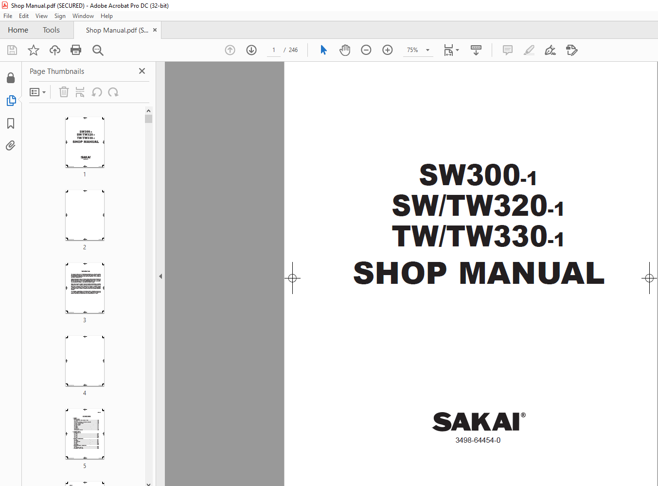
Sakai Vibrating Roller SW300-1 / SWTW320-1 / TWTW330-1 Shop Manual (3498-64454-0)
Sakai Vibrating Roller SW300-1 / SWTW320-1 / TWTW330-1 Shop Manual (3498-64454-0) – PDF DOWNLOAD
FILE DETAILS:
Sakai Vibrating Roller SW300-1 / SWTW320-1 / TWTW330-1 Shop Manual (3498-64454-0) – PDF DOWNLOAD
Language : English
Pages :246
Downloadable : Yes
File Type : PDF
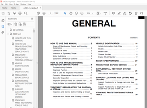
TABLE OF CONTENTS:
Sakai Vibrating Roller SW300-1 / SWTW320-1 / TWTW330-1 Shop Manual (3498-64454-0) – PDF DOWNLOAD
1. SAFETY
1. GENERAL SAFETY
1-1. Understanding the Safety Symbols and Words 1-001
1-2. General 1-001
1-3. Qualifi cations of Operators and Maintenance Personnel 1-002
1-4. Safety Practices and Policies1-002
1-5. Pre Start Inspection 1-003
1-6. Safety Instructions 1-003
1-7. Starting 1-004
1-8. Operating 1-004
1-9. Stopping 1-004
1-10. Maintenance 1-005
1-11. Transporting the Machine 1-007
2. SPECIFICATIONS
1. SPECIFICATION DATA
1-1. SW300-1 2-001
1-2. SW320-1 2-003
1-3. SW330-1 2-005
1-4. TW320-1 2-007
1-5. TW330-1 2-009
2. TABLE OF STANDARD VALUES
2-1. Engine 2-011
2-2. Propulsion 2-011
2-3. Hydraulic System 2-012
2-4. Steering 2-012
2-5. Brakes 2-013
2-6. Capacities 2-013
3. FUEL AND LUBRICANTS SPECIFICATION
3-1. Rating 2-014
3-2. Recommended Lubricants 2-014
4. TIGHTENING TORQUE CHART 2-015
00_Hyo1_Intro_Contents.indd 005 2012/11/20 8:11:18
SW300-1 ○0
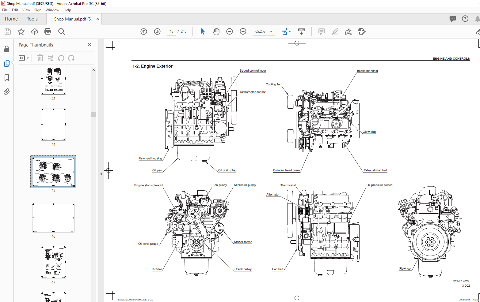
3. ENGINE AND CONTROLS
1. ENGINE
1-1. Engine Mount 3-001
1-2. Engine Exterior 3-002
2. CONTROL SYSTEM
2-1. Throttle Control 3-003
2-2. Forward-reverse Control 3-004
3. PUMP MOUNT
3-1. Pump Mount 3-005
3-1-1. Installation of pump 3-006
4. HYDRAULIC SYSTEMS
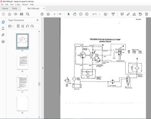
1. SYSTEM CIRCUIT DIAGRAM
1-1. Graphic Symbols for Hydraulic Circuits 4-001
1-2. Hydraulic Circuit Diagram4-003
1-2-1. Hydraulic circuit diagram (SW types) 4-003
1-2-2. Hydraulic circuit diagram (TW types)4-004
2. PROPULSION HYDRAULIC SYSTEM
2-1. Propulsion Hydraulic Piping 4-005
2-1-1. Propulsion hydraulic piping (1) (SW types: main) 4-005
2-1-2. Propulsion hydraulic piping (1) (TW types: main) 4-006
2-1-3. Propulsion hydraulic piping (2) (SW/TW types: front) 4-007
2-1-4. Propulsion hydraulic piping (3) (SW types: rear) 4-008
2-1-5. Propulsion hydraulic piping (3) (TW types: rear) 4-009
2-2. Hydraulic Component Specifi cations 4-010
2-2-1. Propulsion pump 4-010
2-2-2. Propulsion hydraulic motor (SW types: front and rear, TW types: front) 4-012
2-2-3. Propulsion hydraulic motor (TW types: rear) 4-013
2-2-4. Differential lock valve (TW types) 4-014
3. VIBRATOR HYDRAULIC SYSTEM
3-1. Vibrator Hydraulic Piping 4-015
3-1-1. Vibrator hydraulic piping (1) (SW types: main) 4-015
3-1-2. Vibrator hydraulic piping (1) (TW types: main) 4-016
3-1-3. Vibrator hydraulic piping (2) (SW/TW types: front) 4-017
3-1-4. Vibrator hydraulic piping (3) (SW types: rear) 4-018
3-2. Hydraulic Component Specifi cations 4-019
3-2-1. Vibrator pump 4-019
3-2-2. Vibrator hydraulic motor 4-020
3-2-3. Vibrator solenoid valve 4-021
00_Hyo1_Intro_Contents.indd 006 2012/11/20 8:11:18
SW300-1 ○0
4. STEERING SYSTEM
4-1. Steering Hydraulic Piping 4-022
4-2. Steering Wheel 4-023
4-3. Hydraulic Component Specifi cations 4-024
4-3-1. Steering charge pump 4-024
4-3-2. Orbitrol 4-025
4-4. Frame (Center Pin) 4-026
5. ELECTRICAL SYSTEM
1. SYSTEM CIRCUIT DIAGRAM
1-1. Electrical Circuit Diagram (SW types) 5-001
1-2. Electrical Circuit Diagram (TW types) 5-002
2. ELECTRICAL COMPONENTS
2-1. Electrical Component Layout 5-003
3. ELECTRICAL COMPONENT SPECIFICATIONS
3-1. Fuse Box 5-004
3-2. Combination Meter 5-005
6. VIBRATORY DRUM ・ REAR WHEEL
1. PRECAUTIONS FOR DISASSEMBLY AND REASSEMBLY 6-001
2. VIBRATORY DRUM
2-1. Removal and Installation of Vibratory Drum 6-003
2-1-1. Removal of front vibratory drum 6-004
2-1-2. Removal of rear vibratory drum 6-006
2-1-3. Removal of plate 6-008
2-1-4. Installation of vibratory drum 6-009
3. VIBRATORY DRUM ASSY
3-1. Vibratory Drum ASSY 6-010
3-2. Disassembly and Reassembly of Vibratory Drum 6-011
3-2-1. Disassembly of vibratory drum 6-011
3-2-2. Reassembly of vibratory drum 6-021
4. REAR AXLE
4-1. Rear Axle ASSY (TW Types) 6-039
4-2. Removal and Installation of Rear Axle (TW Types) 6-040
4-2-1. Removal of rear axle 6-041
4-2-2. Installation of rear axle 6-044
00_Hyo1_Intro_Contents.indd 007 2012/11/20 8:11:18
SW300-1 ○0
7. BRAKE
1. BRAKE PEDAL 7-001
2. BRAKE SYSTEM 7-002
2-1. SW types 7-002
2-2. TW types 7-003
8. SPRAY SYSTEMS
1. WATER SPRAY SYSTEM 8-001
1-1. Water Spray Piping (SW types) 8-001
1-2. Water Spray Piping (TW types) 8-002
2. LIQUID SPRAY SYSTEM (TW TYPES) 8-003
9. INSPECTION AND ADJUSTMENT
1. INSPECTION AND ADJUSTMENT
1-1. Safety Precautions for Inspection and Adjustment 9-001
1-2. Preparation for Inspection and Adjustment 9-001
1-3. Precautions for Inspection and Adjustment 9-001
1-4. Warm-up 9-001
1-5. Inspection and Adjustment of Engine Related Items 9-001
2. MEASUREMENT AND INSPECTION OF PROPULSION CIRCUIT PRESSURE
2-1. Measurement 9-002
2-2. Inspection 9-003
3. MEASUREMENT AND ADJUSTMENT OF PROPULSION CHARGE CIRCUIT
PRESSURE
3-1. Measurement 9-004
3-2. Adjustment 9-005
4. MEASUREMENT OF PARKING BRAKE RELEASE PRESSURE
4-1. Measurement 9-006
4-1-1. SW types: front and rear, TW types: front 9-006
4-1-2. TW types: rear 9-007
5. MEASUREMENT OF VIBRATOR CIRCUIT PRESSURE
5-1. Measurement (SW types: front and rear, TW types: front) 9-008
6. MEASUREMENT AND INSPECTION OF STEERING CIRCUIT PRESSURE
6-1. Measurement 9-009
6-2. Inspection 9-010
7. MEASUREMENT OF HYDRAULIC PUMP CASE PRESSURE
7-1. Measurement of Propulsion Pump Case Pressure 9-011
00_Hyo1_Intro_Contents.indd 008 2012/11/20 8:11:18
SW300-1 ○0
8. MEASUREMENT OF PROPULSION MOTOR CASE PRESSURE
8-1. Measurement 9-012
8-1-1. SW types: front and rear, TW types: front 9-012
8-1-2. TW types: rear 9-013
9. ADJUSTMENT OF THROTTLE LEVER LINKAGE
9-1. Adjustment 9-014
10. ADJUSTMENT OF F-R LEVER LINKAGE
10-1. Adjustment 9-015
10. TROUBLESHOOTING
1. TROUBLESHOOTING
1-1. Safety Precautions for Troubleshooting 10-001
1-2. Important Information for Troubleshooting 10-001
1-3. Before Starting 10-002
1-4. Wire Color Code and Number 10-002
2. ELECTRICAL SYSTEM TROUBLESHOOTING
2-1. When Performing Electrical System Fault Diagnosis 10-003
2-1-1. Precautions to take during electrical circuit fault diagnosis 10-003
2-1-2. Inspection procedures using a tester 10-004
2-1-3. Inspection of electrical system 10-009
2-2. Engine 10-012
2-2-1. Engine will not start (Starter motor does not run) 1/2 10-012
2-2-1. Engine will not start (Starter motor does not run) 2/2 10-014
2-2-2. Engine will not start (But starter motor runs) 10-016
2-2-3. Engine does not stop running 10-016
2-2-4. No charging 10-018
2-2-5. Glow plug is not heated (Engine starting performance is bad in
cold weather) 10-018
2-2-6. Starter motor runs even when F-R lever is not at “N” 10-018
2-3. Propulsion 10-020
2-3-1. Machine moves neither forward nor backward 10-020
2-3-2. Brake cannot be released 10-022
2-3-3. Brake does not work 10-024
2-4. Vibration 10-026
2-4-1. No vibration occurs 10-026
2-4-2. Vibration mode cannot be switched (F-R lever vibration switch does
not work) 10-028
00_Hyo1_Intro_Contents.indd 009 2012/11/20 8:11:18
SW300-1 ○0
2-5. Spray System 10-030
2-5-1. Water spray does not operate 10-030
2-5-2. Liquid spray does not operate (TW types) 10-032
2-6. Lighting 10-034
2-6-1. Head lamp does not light 10-034
2-6-2. Illumination of combination meter does not turn on 10-036
2-6-3. Combination meter warning lamp or indicator lamp is abnormal 10-036
2-6-4. Tachometer reading is abnormal 10-038
2-6-5. Hour meter is abnormal 10-038
2-6-6. Temperature meter is abnormal 10-040
2-6-7. Fuel meter is abnormal 10-040
2-6-8. Hydraulic oil fi lter warning lamp remains ON 10-042
2-6-9. Engine oil pressure warning lamp remains ON 10-042
2-6-10. Vibration indicator lamp does not light 10-044
2-6-11. Parking brake indicator lamp does not light 10-046
2-6-12. Water spray indicator lamp does not light 10-048
2-6-13. Liquid spray indicator lamp does not light (TW types) 10-048
2-6-14. Preheating indicator lamp does not light 10-050
2-6-15. Horn does not sound 10-052
2-6-16. Backup buzzer does not sound 10-052
3. HYDRAULIC SYSTEM TROUBLESHOOTING
3-1. When Performing Hydraulic System Troubleshooting 10-053
3-2. Propulsion System 10-054
3-2-1. Machine moves neither forward nor backward 1/2 10-054
3-2-1. Machine moves neither forward nor backward 2/2 10-055
3-2-2. Machine moves in one direction only (forward or backward) 10-055
3-2-3. Slow machine speed or small drive force 1/2 10-055
3-2-3. Slow machine speed or small drive force 2/2 10-056
3-2-4. Machine does not stop completely with F-R lever in “N” 10-056
3-2-5. Driving not possible with differential locked (TW types) 10-056
3-2-6. Propulsion system is overheating 10-057
3-2-7. Abnormal noise from propulsion system 10-057
3-3. Vibrator System 10-058
3-3-1. No vibration 10-058
3-3-2. Vibrator frequency is too low 10-059
3-3-3. Vibrator does not stop 10-059
3-3-4. Vibrator system is overheating 10-059
3-3-5. Abnormal noise from vibrator system 10-060
00_Hyo1_Intro_Contents.indd 010 2012/11/20 8:11:18
SW300-1 ○0
3-4. Steering System 10-061
3-4-1. Steering wheel is hard to turn 10-061
3-4-2. Steering response is slow 10-061
3-4-3. Steering wheel backlash or play is large 10-062
3-4-4. Steering system is overheating 10-062
3-4-5. Abnormal noise from steering system 10-062
IMAGES PREVIEW OF THE MANUAL:
More products