$36
Sakai Vibrating Roller SW352 TW352 Shop Manual - PDF DOWNLOAD
Sakai Vibrating Roller SW352, TW352 Shop Manual – PDF DOWNLOAD
FILE DETAILS:
Sakai Vibrating Roller SW352, TW352 Shop Manual – PDF DOWNLOAD
Language : English
Pages :176
Downloadable : Yes
File Type : PDF
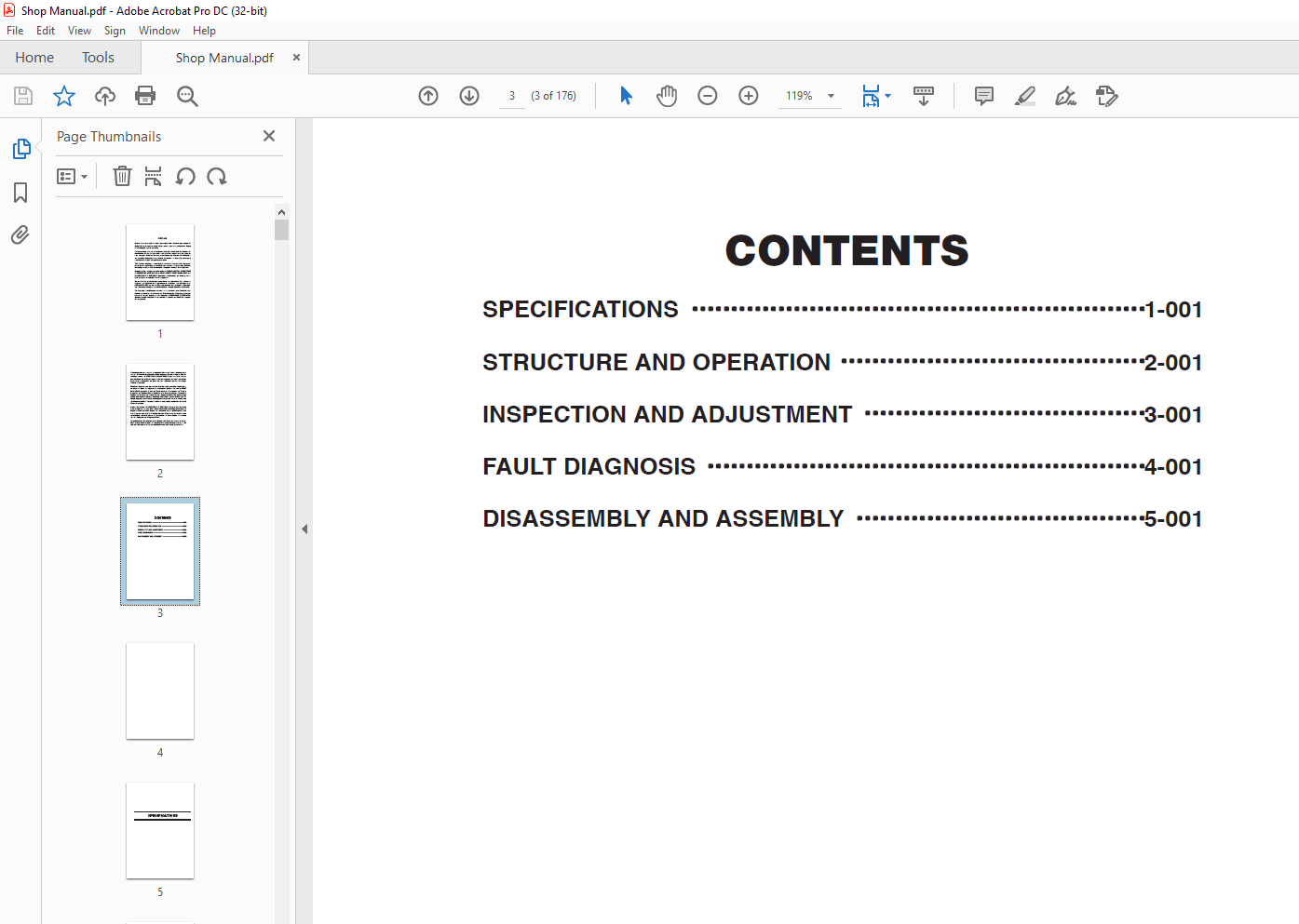
TABLE OF CONTENTS:
Sakai Vibrating Roller SW352 TW352 Shop Manual – PDF DOWNLOAD
SPECIFICATIONS・・・・・・・・・・・・・・・・・・・
STRUCTURE AND OPERATION・・・
INSPECTION AND ADJUSTMENT
FAULT DIAGNOSIS・・・・・・・・・・・・・・・・・
DISASSEMBLY AND ASSEMBLY ・
1. Location of Engine-related Units
1-1. Engine mount 2-003
1-2. Intake system 2-004
1-3. Intake system 2-005
1-4. Exhaust system 2-006
1-5. Exhaust system 2-007
1-6. Cooling piping and radiator 2-008
1-7. Fuel piping and fuel tank 2-009
1-8. Fuel controls 2-010
2. Description and Operation of Hydraulic System
2-1. Hydraulic pump
2-1-1. Propulsion pump assembly 2-011
2-1-2. Rear vibrator pump assembly (SW352, SW502) 2-012
2-1-3. Front vibrator pump assembly and steering/charge pump assembly 2-013
2-1-4. Hydraulic circuit diagram (SW352) 2-014
2-1-5. Hydraulic circuit diagram (SW502) 2-015
2-1-6. Hydraulic circuit diagram (TW352) 2-016
2-1-7. Hydraulic circuit diagram (TW502) 2-017
2-2. Propulsion line
2-2-1. Hydraulic piping (front) 2-018
2-2-2. Hydraulic piping (rear) 2-019
2-2-3. Hydraulic piping (rear) 2-020
2-2-4. Propulsion motor (cam motor) assembly (front) 2-021
2-2-5. Propulsion motor (cam motor) assembly (rear) 2-022
2-2-6. Description and operation of cam motor 2-023
2-2-7. Rear axle assembly (TW352, TW502) 2-027
2-2-8. Propulsion controls 2-028
2-2-9. Propulsion circuit diagram (SW352, SW502) 2-029
2-2-10. Propulsion circuit diagram (TW352, TW502) 2-030
2-2-11. Description and operation of propulsion system 2-031
2-3. Vibrating system
2-3-1. Hydraulic piping (SW352) 2-036
2-3-2. Hydraulic piping (SW502) 2-037
2-3-3. Hydraulic piping (TW352) 2-038
2-3-4. Hydraulic piping (TW502) 2-039
2-3-5. Vibrator motor assembly 2-040
2-3-6. Radiator fan motor assembly 2-041
2-3-7. Vibrator (SW352, TW352) 2-042
2-3-8. Vibrator (SW502, TW502) 2-043
2-3-9. Vibrator circuit diagram (SW352, TW352) 2-044
2-002
2-3-10. Vibrator circuit diagram (SW502, TW502) 2-045
2-3-11. Description and operation of vibrating system 2-046
2-4. Steering system
2-4-1. Hydraulic piping 2-048
2-4-2. Steering valve (Orbitrol) 2-049
2-4-3. Steering cylinder assembly 2-050
2-4-4. Steering circuit diagram 2-051
2-4-5. Description and operation of steering circuit 2-052
3. Brake System
3-1. Brake pedal 2-053
3-2. Description and operation of parking brake (negative brake) circuit 2-054
4. Sprinkler
4-1. Sprinkler piping 2-055
5. Liquid Sprayer
5-1. Liquid sprayer piping 2-056
6. Electric System
6-1. Location of instrument panel and key units 2-057
6-2. Location of key units 2-058
6-3. Electric wiring diagram (SW352) 2-059
6-4. Electric wiring diagram (TW352) 2-060
6-5. Electric wiring diagram (SW502) 2-061
6-6. Electric wiring diagram (TW502) 2-062
IMAGES PREVIEW OF THE MANUAL:
More products