$35
Sakai Vibrating Roller SW651 Series Shop Manual - PDF DOWNLOAD
Sakai Vibrating Roller SW651 Series Shop Manual - PDF DOWNLOAD
Language : English
Pages :122
Downloadable : Yes
File Type : PDF
TABLE OF CONTENTS:
Sakai Vibrating Roller SW651 Series Shop Manual - PDF DOWNLOAD
SPECIFICATIONSSTRUCTURE & OPERATIONINSPECTION & ADJUSTMENTTROUBLE-SHOOTING
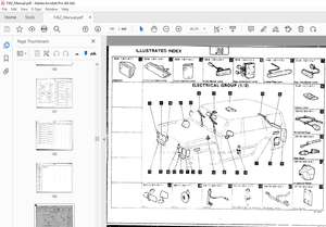
1 Location of Engine-related Key Units
1-1 Engine mount
1-2 Intake system
1-3 Exhaust system
1-4 Cooling piping & radiator
1-5 Fuel piping & fuel tank
1-6 Fuel controls2 Description and Operation of Hydraulic System
2-1 Construction and operation of hydraulic pump
2-1-1 Coupling
2-1-2 Pump ass'y (Propulsion+Vibrator drive+Steering) 2-1-3 Hydraulic
circuit (SW651, S651ND)
2-1-4 Hydraulic circuit (SW651B)
2-2 Propulsion line
2-2-1 Propulsion motor
2-2-2 Hydraulic piping ( I )
2-2-3 Hydraulic piping (II) (SW651, SW651ND)
2-2-4 Hydraulic piping (III) (SW651B)
2-2-5 Split drum (SW651 B)
2-2-6 Description and operation of split drum (SW651B)
2-2-7 Propulsion controls
2-2-8 Propulsion circuit (SW651, SW65ND)
2-2-9 Propulsion circuit (SW651B)
2-3-10 Description and operation of propulsion system
2-3 Vibrating system
2-3-1 Vibrator motor
2-3-2 Hydraulic piping ( I )
2-3-3 Hydraulic piping (II)
2-3-4 Vibrator (SW651)
2-3-5 Vibrator (SW651 B)
2-3-6 Vibrator (SW651 ND)
2-3-7 Vibration generating mechanism (SW651, SW651B)
2-3-8 Mechanism for switching horizontal and normal vibration (SW651ND)
2-3-9 Vibrator circuit
2-3-10 Description and operation of vibrating system
2-4 Steering system
2-4-1 Steering piping
2-4-2 Steering valve (Orbitrol)
2-4-3 Description and opertion of Orbitrol)2-4-4 Frame (center pin)
2-4-5 Steering cylinder
2-4-6 Steering circuit3 Brake System
3-1 Brake system (brake pedal}
3-2 Description and operation of brake circuit4 Sprinkler
4-1 Sprinkler piping
5Electric System
5-1 Layout of panel and relays 5-2 Location of electric
components 5-3 Electric wiring diagram
IMAGES PREVIEW OF THE MANUAL:
More products