$42
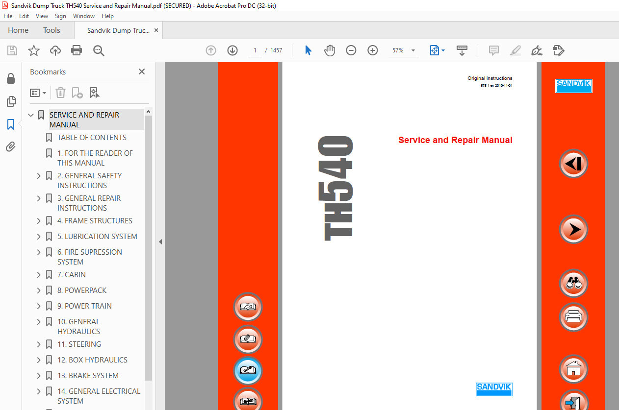
Sandvik Mining TH540 Service and Repair Manual – PDF DOWNLOAD
Sandvik Mining TH540 Service and Repair Manual – PDF DOWNLOAD
FILE DETAILS:
Sandvik Mining TH540 Service and Repair Manual – PDF DOWNLOAD
Language : English
Pages :1457
Downloadable : Yes
File Type : PDF
TABLE OF CONTENTS:
Sandvik Mining TH540 Service and Repair Manual – PDF DOWNLOAD
SERVICE AND REPAIR MANUAL 1
TABLE OF CONTENTS 3
1 FOR THE READER OF THIS MANUAL 15
2 GENERAL SAFETY INSTRUCTIONS 17
21 General safety precautions during operations 19
22 Warning and information symbols used in this manual 19
221 Safety Symbols Pertaining to the Machine 20
3 GENERAL REPAIR INSTRUCTIONS 25
31 Location of main switch 27
32 Hydraulics maintenance 28
33 Electric system maintenance 29
34 Battery maintenance 30
35 Welding 32
36 Blocking the machine for repair procedures 33
37 Lifting methods and lifting points 34
4 FRAME STRUCTURES 37
41 Locking devices 38
411 How to install frame locking bar 39
412 How to remove frame locking bar 40
413 How to install the box support bar 41
414 How to remove the box support bar 42
42 Middle hinge joint 43
421 Design features of upper hinge 43
422 Design features of lower hinge 44
423 Disassembly of middle hinge joints 46
424 Assembly of the middle hinge joint 51
425 Adjusting of middle hinge joint 56
43 Oscillating axle 57
431 Disassembly of oscillating axle 59
432 Assembly of oscillating axle 61
433 Oscillating cradle bushing replacement 62
44 Pins 63
441 Design features of the pins 63
442 Pin removal 64
443 Pin removal with a puller 64
444 Pin removal without special tools 65
445 Pin installation 65
45 Removing the box 66
46 Installing the box 68
47 Welding 69
471 Precautions before welding 70
472 Basic quality requirements 70
473 Frame welding 71
474 Box welding 71
475 Edge preparation 72
476 Working temperature and pre-heating 73
477 Heat-input – number of welding passes 74
478 Welding to other steels 75
479 Gas cutting 77
5 LUBRICATION SYSTEM 79
51 System description 81
511 Safety interlocks 81
512 Inputs 82
513 Outputs 82
52 Functional description of the components 83
521 Removing the lubrication unit 85
522 Installing the lubrication unit 88
53 Checking and adjusting 91
531 Forced functions (requires service password) 91
532 Diagnostics 94
533 Filling the central lube reservoir 94
534 Bleeding the pump 95
535 Main piping 95
536 Doser adjustment 96
54 General troubleshooting 97
541 VCM-System troubleshooting 98
6 FIRE SUPRESSION SYSTEM 101
61 Ansul 102
611 Main components 102
612 System description 103
613 Inputs 103
614 Outputs 103
615 Specifications 103
616 System components 104
617 Location of nozzles 105
618 Ansul system operation 106
619 Ansul Checkfire system (optional) 107
62 Sandvik FS 1000 109
621 Main components 109
622 System description 110
623 Inputs 110
624 Outputs 110
625 System components 111
626 Specifications 111
627 Location of nozzles 112
628 System operation 113
63 Checking and adjusting 115
631 Forced functions 115
632 Diagnostics 118
64 VCM-System troubleshooting 119
7 CABIN 121
71 Instrument panel 124
72 Functional description of components 125
721 Steering wheel 125
722 Box control 125
723 Combination switch 125
724 Brake pedal 126
725 Throttle pedal 126
726 Door switch 127
73 Heating and air conditioning system 128
731 System description 129
732 Component descriptions 130
74 Window washer and wiper 131
741 Inputs 131
742 Outputs 131
743 Removing the wiper motor assembly 132
744 Installing the wiper motor assembly 132
75 Removing the cabin 133
76 Installing the cabin 137
77 Removing the cabin seat 139
78 Installing the cabin seat 140
79 Removing the cabin window 140
710 Installing the cabin window 141
711 Removing the cabin door 142
712 Installing the door to the cabin 143
713 Checking and adjusting 144
7131 Testing the door switch 144
7132 Testing the buttons 144
7133 Forced functions 145
7134 Throttle pedal calibration 148
7135 Diagnostics 149
714 VCM-System troubleshooting 150
8 POWERPACK 155
81 Engine 157
811 Technical data 157
812 Technical data 159
813 System description 160
814 Explanation of concepts 161
815 Starting and shutting down the engine 162
816 Over-rev protection 164
817 Jump-starting 165
818 Restarting an Out of Fuel Engine 166
819 Check stop engine and engine codes 168
8110 Changing engine oil and filters 171
8111 Engine mounts inspection 173
8112 Removing the powerpack 175
8113 Installing the powerpack 182
82 Fuel system 186
821 System description 186
822 Fuel filters 187
823 Fuel lines 188
824 Fuel gauge 188
83 Air Cleaner system 189
831 System description 189
832 Air filter 190
833 Restriction indicator 191
84 Exhaust system 191
841 System description 191
842 Exhaust piping 192
843 Exhaust purifier 192
844 Servicing the exhaust purifier 193
845 Removing the exhaust purifier 193
846 Installing the exhaust purifier 193
85 Turbocharger 194
851 Servicing the turbocharger 194
852 Removing the turbocharger 195
853 Fitting the turbocharger 196
86 Pumps 197
87 Cooling system 198
871 Main components of the engine coolers 198
872 System description 199
873 Functional description of components 200
874 Cleaning the engine cooler cores 203
875 Engine cooler tube and sealing removal 206
876 Removing the engine radiator assembly 208
877 Installing the engine radiator assembly 211
878 Removing the engine charge air cooler assembly 214
879 Installing the engine charge air cooler assembly 218
8710 Removing the engine thermostat 221
8711 Installing the engine thermostat 223
88 Checking and adjusting 224
881 Checking of the blower pump pressures 224
882 Forced functions 229
883 Diagnostics 231
89 General troubleshooting 232
810 VCM-System troubleshooting 233
9 POWER TRAIN 237
91 System description 238
92 Transmission hydraulics 239
93 Transmission 240
931 Gearbox 240
932 Transmission filter unit 241
933 Gear selection 242
934 Transmission shaft speed sensor 243
935 Controlling manual transmission 244
936 Controlling automatic transmission 245
937 Filling instructions 246
938 Removing the transmission 248
939 Installing the transmission 252
9310 General troubleshooting 255
94 Transmission cooling 256
941 System description 257
942 Removing and installing the transmission oil heat exchanger 257
95 Torque converter 257
951 System description 258
952 Functional description of the components 259
953 Converter lock 261
954 Torque converter change 262
96 Jake brake (option) 265
961 Exhaust brake, Jake brake (option) 266
97 Retarder (option) 267
971 Electric retarder, Telma (option) 267
972 Servicing electric retarder 268
98 Wheels 269
981 Removing the wheels 270
982 Installing the wheels 276
983 Rim 278
984 Structures and functions of the off-road tyre components 279
985 Tire dismounting from rim 281
986 Rim Inspection 283
987 Tire vertical mounting on rim 284
99 Axles 285
991 Technical data 286
992 Planetary hub and differential oil change 289
993 Tightening torques of power train flanges and bolts 291
994 Removing of the rear axle 292
995 Installing the rear axle 296
996 Removing the front axle assembly 300
997 Installing the front axle assembly 304
998 Disassembling the wheel ends 307
999 Assembling wheel ends 308
910 Cardan shafts 309
9101 General Maintenance and Inspection 309
9102 Removing the cardan shaft 310
9103 Installing the cardan shaft 311
911 Checking and adjusting 312
9111 Measuring speed and travelled distance, and sensor diagnostics 312
9112 Measuring the transmission pressure 314
9113 Forced functions 315
9114 Diagnostics 318
9115 The measurement data of the modules 319
912 VCM-System troubleshooting 320
10 GENERAL HYDRAULICS 325
101 Hydraulic oil 326
102 Hydraulic diagram 327
103 General hydraulic maintenance 329
1031 General troubleshooting 330
1032 Basic causes of hydraulic system failures 331
1033 Checking hydraulic system for leaks 332
1034 Low temperature starting 332
1035 Prevent of cavitation formation 333
1036 Oil filters 333
1037 Servicing filters and strainers 333
1038 Level of oil in tank 333
1039 Oil storage and handling 334
104 Hydraulic oil tanks 335
1041 Design features 335
1042 Filter diagnostics 337
1043 Functional description of components 338
1044 Level sensors for the oil tanks 339
1045 To change filter element 340
1046 Changing oil in the hydraulic system 341
1047 Repairing the tank 345
1048 Hydraulic tank cover resealing 346
105 Suction lines 349
1051 Design features 349
1052 Bleeding the suction lines 350
106 Hydraulic pressure test points 351
107 Hoses and tubing 357
1071 Marking of hydraulic hoses 358
108 Pressure accumulators 359
1081 Recharging piston accumulators 360
1082 Disassembly and assembly of the piston accumulator 361
1083 Recharging diaphragm accumulators 363
109 Hydraulic oil cooler and return lines 365
1091 System description 366
1092 Functional description of the components 367
1093 Cleaning the hydraulic cooler cores 368
1094 Removing the hydraulic oil cooler 369
1095 Installing the hydraulic oil cooler 372
1096 Removing the hydraulic cooler fan motor 374
1097 Installing the hydraulic cooler fan motor 376
1010 Pumps 378
10101 Piston type pump 379
10102 Piston type double pump 380
10103 Starting new pumps 381
10104 Removing the pump P2112 382
10105 Installing the pump P2112 384
10106 Removing the double pump P202 386
10107 Installing the double pump P202 388
1011 Checking and adjusting 390
10111 Measuring the temperatures of the brake, hydraulic and transmission oil 391
10112 Forced functions 393
1012 VCM-System troubleshooting 396
1013 Hydraulic component symbols 400
11 STEERING 407
111 Main components 408
112 Hydraulic diagram 409
113 System description 411
1131 Safety interlocks 411
1132 Inputs 411
1133 Outputs 411
114 Functional description 412
1141 Steering main valve (automation) 412
1142 Steering main valve (manual) 412
1143 Directional valve 413
1144 Orbitrol assembly 413
1145 Steering cylinder 414
1146 Steering pump 414
1147 Steering limit switch (optional) 414
1148 Pressure relief valve 414
115 Emergency steering (option) 415
1151 System description of VCM 415
1152 Functional description of components 416
1153 Safety interlocks 416
1154 Inputs 416
1155 Outputs 417
116 Steering cylinder 418
1161 Removing the steering cylinder 420
1162 Installing the steering cylinder 423
1163 Cylinder disassembly 425
1164 Inspection and repair 426
1165 Reassembly and installation 426
1166 Removing the steering main valve 427
1167 Installing the steering main valve 429
117 Checking and adjusting 430
1171 Checking and adjusting of the steering / tipping pump pressures 430
1172 Checking and adjusting steering valve pressures 433
1173 Steering cylinder bypass test 437
1174 Forced functions 443
1175 Diagnostics 446
118 VCM-System troubleshooting 449
12 BOX HYDRAULICS 453
121 Main components 454
122 Hydraulic diagram 455
123 System description 456
1231 Box control 456
1232 Ejector box control 458
124 Functional description of components 459
1241 Tipping valve 459
1242 Tipping cylinder 459
1243 Pump P201 460
1244 Return filter 460
1245 Other box hydraulic components 460
125 Box counter 461
1251 Inputs 461
1252 Outputs 461
126 Tipping cylinders 462
1261 Removing the tipping cylinder hoses 463
1262 Installing the tipping cylinder hoses 466
1263 Removing the tipping cylinder 468
1264 Installing the tipping cylinder 471
1265 Tipping cylinder disassembly 473
1266 Inspection and repair 473
1267 Reassembly and installation 474
127 Checking and adjusting 475
1271 Checking of the steering / box hydraulic pump pressures 475
1272 Checking of the box valve pressures 476
1273 Tipping cylinders leakage test 480
1274 Forced functions 487
1275 Diagnostics 489
1276 Testing the movement of the control joystick 490
1277 Control joystick calibration 491
1278 The measurement data of the modules 492
128 VCM-System troubleshooting 493
13 BRAKE SYSTEM 497
131 Main components 498
132 Hydraulic diagram 499
133 System description 500
1331 Service and parking brake inputs 502
1332 Service and parking brake outputs 502
134 Functional description of components 503
1341 Brake charging valve 503
1342 Sequence valve 504
1343 Filter unit 504
1344 Brake pedal valve 506
1345 Brake release pump unit 507
1346 Pressure accumulators 508
135 Brake flushing 509
1351 Hydraulic diagram, brake flushing 510
1352 System description 511
1353 Functional description of components 511
136 Automatic Brake Activation 512
1361 Automatic Brake Activation tests 512
1362 Transmission pressure sensor test 513
1363 Automatic parking brake engaging test (low brake charging pressure) 514
137 Neutral brake 515
1371 Inputs 515
1372 Outputs 515
138 Disassembly of brakes 516
139 Assembly of brakes 517
1310 Checking and adjusting 517
13101 Brake flushing pressure check 518
13102 Brake pump pressure check / adjustment 519
13103 Brake charging valve pressure check 522
13104 Parking brake test 524
13105 Service brake pedal test 526
13106 Accepting the brake test results 528
13107 Brake test log entries 529
13108 Aborted brake test 530
13109 Brake friction disc lining wear check procedure 531
131010 Brake Slack Adjuster Adjustment (Posi-Stop) 533
131011 Testing the brake accumulator 535
131012 Measuring the brake accumulator precharge pressure P0 536
131013 Measuring brake pressures 538
131014 Measuring brake temperatures 540
131015 Forced functions 541
131016 Diagnostics 545
1311 VCM-System troubleshooting 548
14 GENERAL ELECTRICAL SYSTEM 559
141 System description 560
142 Lights 561
1421 Front lights 561
1422 Reversing lights 562
1423 Parking lights 562
1424 Brake lights and blinkers 563
1425 Cabin corner lights 564
1426 Loading lights 564
1427 Warning light (beacon) 565
1428 Warning brake light 565
1429 Direction indicator lights 566
143 Horn signal and reversing warning 566
1431 Horn signal 566
1432 Alarm signal and lights for reversing 567
144 Emergency stop 567
1441 Inputs 567
1442 Outputs 567
145 Warning and alarm condition 568
1451 Inputs & outputs 569
146 Batteries 570
1461 Battery technical data 570
1462 Removing the batteries 574
1463 Installing the batteries 576
147 Alternator 578
1471 Removing the alternator 579
1472 Installing the alternator 581
148 Twin alternator 583
1481 Removing the twin alternator 584
1482 Installing the twin alternator 585
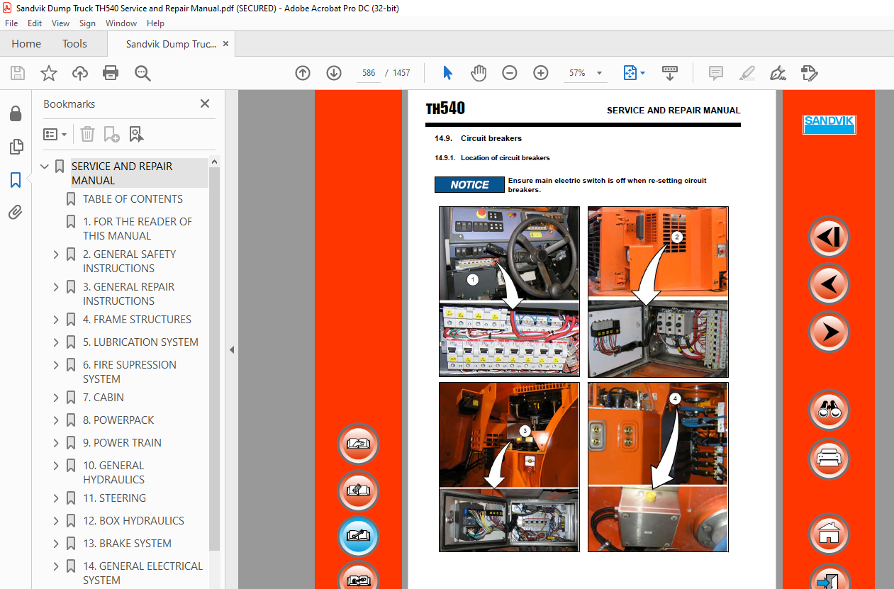
149 Circuit breakers 586
1491 Location of circuit breakers 586
1492 Circuit breakers descriptions and values 587
1410 Vehicle Control and Management system user interface 589
14101 Using the display module 589
14102 Symbols on the display windows 590
14103 Main window 596
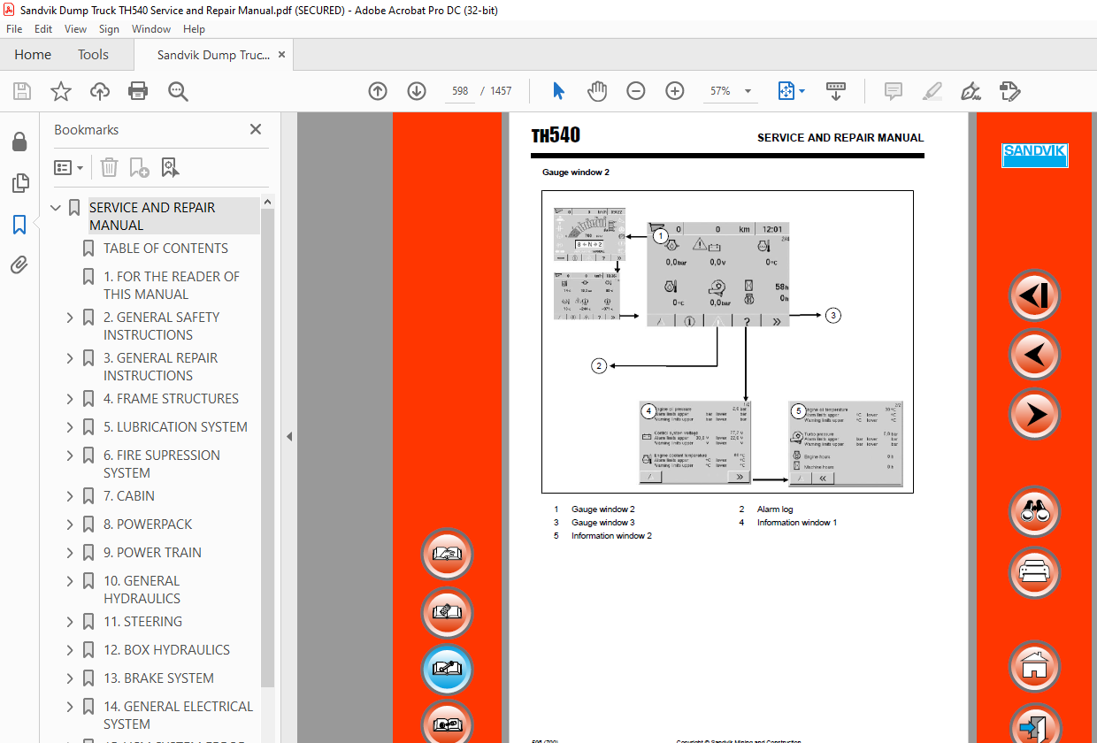
14104 Gauge windows 597
14105 Alarm log 601
14106 Service windows for the operator 602
14107 Service windows for service personnel 609
14108 Service password 630
1411 Changing the control modules 631
14111 Location of the VCM-system modules 631
14112 Changing a single I/O module 632
14113 Changing several I/O modules 634
14114 Changing the display module 634
1412 System implementation 635
1413 VCM system self test on start-up 637
14131 Conditions for starting the system (the enable) 637
14132 Alarm log 639
14133 Display information of the Main window and Gauge windows 640
14134 Driving speed and Distance driven measurement and sensor diagnostics 640
1414 Program updating of modules 641
14141 Updating manually the programs of system modules 641
14142 Program updating with PC 641
14143 Programming a new module 642
14144 How to check installation package version 644
1415 How to upload alarm log with update display 644
1416 Checking and adjusting 645
14161 Display settings 645
14162 Status data of the CAN bus 646
14163 Forced functions 647
14164 Diagnostics 652
14165 Checking emergency stop and shutdown system 654
14166 Common rules for checking cables 655
14167 Signal level and scaling of the sensors 656
1417 Controlling additional functions 659
14171 Controlling additional functions in the service window 660
1418 Parameter control 661
14181 Restoring parameters 661
14182 Saving parameters 662
1419 VCM-system troubleshooting 663
1420 How to read electric diagrams 675
14201 Marking 675
14202 Marking of the actuators 676
14203 Parts location 677
14204 The consecutive number 677
14205 Marking of cables 677
14206 Drawing sheets 678
14207 VCM-system module connections 681
1421 Electric diagrams 682
15 VCM SYSTEM ERROR CODES 683
151 Alarm log 684
1511 Error codes 685
16 APPENDICES 697
1 The tightening torques for screws and nuts 701
2 Diaphragm accumulators 703
3 Piston accumulator Operation and Service instructions 709
4 Dana transmission Maintenance / Service manual 727
5 Dana converter Service manual 793
6 Dana axle Service manual 861
61 Posi-Torq – Limited Slip Differential 959
7 Radiator Service manual 991
8 Hydraulic oil cooler Installation and Servicing manual 999
9 Heat exchanger Servicing manual1021
10 Tank breather filter1031
11 Exide battery1037
12 Dana cardan shafts1043
13 Telma1059
14 Donaldson air filter manual1075
15 Wiggins refueling system Technical manual (option)1087
16 Wiggins Installation and Operators manual (option)1103
17 Sandvik FS1000 fire suppression system manuals (option)1119
18 ANSUL fire suppression system Installation, Recharge, Inspection and Maintenance manual1175
19 Function of lubrication system1313
20 Doser groups1319
21 Air conditioner Service1327
22 Update display Operating instructions1369
23 Rexroth piston pump repair instructions1393
24 Weighing system General Workshop Maintenance instruction (option)1419
IMAGES PREVIEW OF THE MANUAL:
S.M 5/24
More products