$41
Sany Crawler Hydraulic Excavator SY195C9 SY205C9 SY215C9 SY225C9 Service Manual – PDF DOWNLOAD
Sany Crawler Hydraulic Excavator SY195C9 SY205C9 SY215C9 SY225C9 Service Manual – PDF DOWNLOAD
FILE DETAILS:
Sany Crawler Hydraulic Excavator SY195C9 SY205C9 SY215C9 SY225C9 Service Manual – PDF DOWNLOAD
Language : English
Pages : 681
Downloadable : Yes
File Type : PDF
IMAGES PREVIEW OF THE MANUAL:
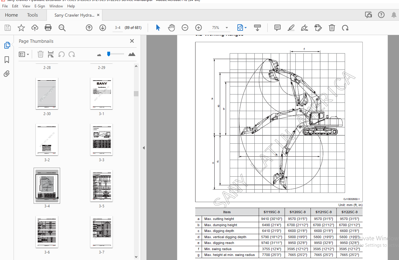
TABLE OF CONTENTS:
Sany Crawler Hydraulic Excavator SY195C9 SY205C9 SY215C9 SY225C9 Service Manual – PDF DOWNLOAD
1 Introduction
1 1 How to Read the Shop Manual 1-3
1 2 Terms for Maintenance Standard 1-5
1 3 Handling Electrical and Hydraulic Components 1-7
1 3 1 Points to remember when handling electric components 1-7
1 3 2 Points to remember when handling hydraulic equipment 1-16
1 4 Hose Connector 1-18
1 4 1 Type of hose connector 1-19
1 4 2 Hose connector tightening torque table 1-19
1 4 3 Connection of O-rings 1-20
1 5 Table of Standard Tightening Torques 1-21
1 6 Type of Bolts 1-22
1 7 Tightening Sequence 1-22
1 8 Maintenance of Half Flanges 1-23
1 8 1 Table of tightening torques for half fl ange bolts 1-23
1 9 Conversion Table 1-24
2 Shop Safety
2 1 Hazard Alert Information 2-3
2 2 General Shop Safety 2-6
2 2 1 Rules and shop behavior 2-7
2 2 2 Housekeeping 2-7
2 2 3 Shop Liquids Storage 2-8
2 2 4 Cleaning Parts 2-8
2 2 5 Jacking Up the Machine 2-9
2 2 6 Electrical Dangers 2-9
2 2 7 Removing Attachments 2-10
2 2 8 Cleaning the Machine 2-10
2 2 9 Using the Correct Tools 2-10
2 2 10 Hoisting a Load 2-11
2 2 11 Appropriate Working Apparel 2-12
2 2 12 Safety Partners 2-12
2 2 13 Two people when engine running 2-13
2 2 14 Driving Pins 2-13
2 2 15 Aligning Parts or Components 2-14
2 2 16 Fire Extinguisher and Emergency Exits 2-14
2 2 17 Personal Protective Equipment 2-14
2 2 18 Running the Machine 2-15
2 2 19 Accumulator 2-16
2 2 20 Adding Fluids to a System 2-16
2 2 21 Track Recoil Springs 2-17
2 2 22 High-Pressure Fluid Lines 2-17
2 2 23 Safe Work Preparations 2-18
2 2 24 Mounting and Dismounting 2-19
2 2 25 Battery Hazards 2-20
2 2 26 Jump-Start Safety 2-21
2 2 27 Disconnecting the System Power 2-21
2 2 28 Lockout/tagout 2-22
2 2 29 Sequence of Procedures 2-22
2 2 30 Chemical hazard 2-24
2 2 31 Material Safety Data Sheets (MSDS) 2-24
2 3 Precautions for sling work and giving signals 2-25
3 Specifi cations
3 1 Dimensions 3-3
3 2 Working Ranges 3-4
3 3 Technical Specifi cations 3-5
3 4 Weight Table 3-8
3 5 Recommended Oil, Fuel and Coolant 3-9
3 6 Capacity Table 3-10
3 7 Engine Performance Curve 3-11
4 Structure and Function
4 1 Engine and Cooling System 4-5
4 1 1 Engine-related parts 4-5
4 1 2 Radiator and intercooler 4-6
4 2 Power Train 4-7
4 2 1 Power transmission system 4-7
4 2 2 Final drive assembly 4-8
4 2 3 Swing machinery 4-11
4 2 4 Swing bearing 4-13
4 3 Undercarriage and Frame 4-14
4 3 1 Track frame and recoil spring 4-14
4 3 2 Idler 4-16
4 3 3 Carrier roller 4-18
4 3 4 Track roller 4-19
4 3 5 Track shoe 4-20
4 3 6 Triple grouser shoe 4-23
4 4 Hydraulic System, Part 1 4-24
4 4 1 Hydraulic equipment layout 4-24
4 4 2 Hydraulic tank and fi lter 4-26
4 4 3 Hydraulic pump 4-27
4 4 4 Pilot pump 4-34
4 4 5 Regulator 4-35
4 4 5 1 Control mechanism makeup 4-37
4 4 5 2 Adjustment of the regulator 4-38
4 4 5 3 Operation 4-40
4 5 Hydraulic System, Part 2 4-43
4 5 1 Control valve 4-43
4 5 2 Operating principle 4-46
4 5 2 1 When spool is in neutral position 4-46
4 5 2 2 Travel 4-48
4 5 2 3 Arm 4-49
4 5 2 4 Boom 4-54
4 5 2 5 Bucket 4-57
4 5 2 6 Swing 4-59
4 5 2 7 Option 4-61
4 5 2 8 Travel straight 4-62
4 5 2 9 Lock valve function 4-63
4 5 2 10 Main relief valve function 4-65
4 5 2 11 Port relief valve function 4-66
4 5 3 Section view 4-70
4 6 Hydraulic System, Part 3 4-81
4 6 1 Swing motor 4-81
4 6 2 Swing holding brake 4-83
4 6 3 Relief valve portion 4-84
4 6 4 Reverse prevention valve 4-86
4 6 4 1 Operation drawing 4-86
4 6 4 2 Explanatory drawing of effects 4-87
4 6 5 Center swivel joint 4-89
4 6 6 Travel motor 4-91
4 6 6 1 Operation of components 4-95
4 6 7 Valve control system 4-107
4 6 8 Pilot valve 4-109
4 6 8 1 Work equipment and swing pilot valve 4-109
4 6 8 2 Travel PPC valve 4-113
4 6 9 Solenoid valve 4-117
4 6 10 Accumulator 4-118
4 6 11 Pilot oil fi lter 4-119
4 6 12 Pump oil pressure sensor 4-120
4 6 13 Hydraulic cylinder 4-121
4 6 14 Work equipment 4-123
4 7 Air Conditioning System 4-129
4 7 1 A/C components layout drawing 4-130
4 7 2 Control panel 4-131
4 7 3 Circuit diagram 4-132
4 7 4 Refrigeration principle 4-134
4 7 4 1 Refrigeration cycle diagram 4-134
4 7 4 2 Heating cycle diagram 4-134
4 7 5 Compressor 4-135
4 7 6 Clutch 4-137
4 7 8 Condenser 4-138
4 7 7 Expansion valve 4-138
4 7 9 Evaporator 4-139
4 7 10 Receiver tank 4-139
4 7 11 Pressure switch 4-140
4 7 12 Fresh air sensor 4-141
4 7 13 Refrigerant 4-141
4 7 14 Compressor oil 4-160
4 8 Engine Control 4-161
4 8 1 System operation 4-162
4 8 2 Components 4-163
4 8 2 1 Fuel control dial 4-163
4 8 2 2 Controller 4-165
4 9 Electrical Control System 4-167
4 9 1 Control function 4-167
4 9 2 Machine control system diagram 4-168
4 9 3 Engine and pump composite control function 4-170
4 9 4 Pump control function 4-174
4 9 4 1 Electrical positive fl ow control 4-175
4 9 4 2 Constant power control 4-178
4 9 5 Valve control function 4-180
4 9 5 1 Bucket fl ow control 4-181
4 9 5 2 Swing priority control 4-182
4 9 6 Duo travel speed control 4-183
4 9 7 Engine preheating/overheating alarm 4-185
4 9 7 1 Engine preheating 4-186
4 9 7 2 Engine overheating alarm 4-187
4 9 8 Engine oil under–pressure alarm 4-187
4 9 9 Auto deceleration/acceleration control 4-188
4 9 10 Engine speed calibration function 4-190
4 9 11 Electrical Components 4-192
4 9 11 1 Pump pressure sensor 4-192
4 9 11 2 Pilot pressure sensor 4-193
4 9 11 3 Engine speed sensor 4-194
4 9 11 4 Coolant temperature sensor 4-195
4 9 11 5 Fuel level sensor 4-196
4 9 11 6 Oil pressure switch 4-197
4 10 Monitoring System 4-198
4 10 1 Machine monitor 4-199
4 10 2 Monitor functions 4-200
4 10 3 Monitor operation 4-203
5 Standard Values
5 1 Standard Values of Engine – related Parts 5-3
5 2 Standard Values of Chassis-related Parts 5-4
6 Testing and Adjusting
6 1 Engine Speed – Test and Calibrate 6-3
6 1 1 Testing 6-3
6 1 2 Adjusting 6-3
6 2 Exhaust Gas Color – Test 6-6
6 3 Valve Clearance – Adjust 6-8
6 3 1 Testing 6-8
6 3 2 Adjusting 6-10
6 4 Compression Pressure – Measure 6-11
6 5 Fuel Injection Timing – Test and Adjust 6-13
6 5 1 Testing 6-13
6 5 2 Adjusting 6-15
6 6 Engine Oil Pressure – Measure 6-17
6 7 Engine Speed Sensor – Adjust 6-19
6 8 A/C Compressor Belt Tension – Test and Adjust 6-20
6 8 1 Testing 6-20
6 8 2 Adjusting 6-20
6 9 Swing Bearing Clearance – Measure 6-22
6 10 Track Tension – Test and Adjust 6-24
6 10 1 Testing 6-24
6 10 2 Adjusting 6-25
6 11 Hydraulic Pressure in Hydraulic Circuits – Test and Adjust 6-26
6 11 1 Measuring 6-26
6 11 2 Adjusting 6-28
6 12 Control Circuit Oil Pressure – Test and Adjust 6-30
6 12 1 Testing 6-30
6 12 2 Adjusting 6-31
6 13 Solenoid Valve Output Pressure – Measure 6-32
6 14 Pilot Valve Output Pressure – Measure 6-34
6 15 Pilot Valves (Work Equipment and Swing) – Adjust 6-36
6 16 Work Equipment Hydraulic Drift – Test 6-37
6 17 Residual Pressure in Hydraulic Circuit – Release 6-40
6 18 Oil Leakage – Measure 6-41
6 19 Air in Each Component – Bleed 6-46
7 Troubleshooting
7 1 Points to Remember When Troubleshooting 7-3
7 2 Troubleshooting Procedures 7-5
7 3 Connector Location and Electrical Circuit Diagram 7-8
7 3 1 Connector location layout 7-12
7 3 2 Electrical element circuit diagram (cab circuit) 7-18
7 3 3 Electrical control circuit diagram (engine circuit) 7-20
7 3 4 Electrical control circuit diagram (sensor and solenoid valve circuit) 7-22
7 3 5 SWP type connector 7-23
7 3 6 A/AMP type connector 7-24
7 3 7 DT type connector 7-25
7 4 Failure Symptoms and Troubleshooting Codes 7-26
7 5 Troubleshooting with an Event Code 7-28
7 6 Troubleshooting of Electrical System (E – Mode) 7-63
7 7 Troubleshooting of Hydraulic and Mechanical Systems (H – Mode) 7-93
8 Disassembly and Assembly
8 1 How to Read This Manual 8-5
8 1 1 Removing and Installing an Assembly 8-5
8 1 2 Disassembling and assembling an assembly 8-5
8 1 3 Special tools 8-5
8 2 1 The symbols used in this section 8-6
8 2 Operating Precautions 8-6
8 3 Start Motor AS – Remove and Install 8-10
8 3 1 Removal 8-10
8 3 2 Installation 8-10
8 4 Injection Pump AS – Remove and Install 8-11
8 4 1 Removal 8-11
8 4 2 Installation 8-13
8 5 Engine Front Seal – Remove and Install 8-15
8 5 1 Removal 8-15
8 5 2 Installation 8-15
8 6 Engine Rear Seal – Remove and Install 8-16
8 6 1 Removal 8-16
8 6 2 Installation 8-17
8 7 Cylinder Head AS – Remove and Install 8-18
8 7 1 Removal 8-18
8 7 2 Installation 8-22
8 8 Radiator AS – Remove and Install 8-24
8 8 1 Removal 8-24
8 8 2 Installation 8-27
8 9 Engine and Hydraulic Pump AS – Remove and Install 8-28
8 9 1 Removal 8-28
8 9 2 Installation 8-34
8 10 Final Drive AS – Remove and Install 8-35
8 10 1 Removal 8-35
8 10 2 Installation 8-36
8 11 Final Drive AS – Disassemble and Assemble 8-37
8 11 1 Disassembly 8-37
8 11 2 Assembly 8-41
8 12 Swing Motor and Swing Drive AS – Remove and Install 8-46
SANY LATIN AMERICA
VIII
Table of Contents SY195/205/215/225C9 Crawler Hydraulic Excavator
Shop Manual – June 2013
8 12 1 Removal 8-46
8 12 2 Installation 8-47
8 13 Swing Motor and Swing Drive AS – Disassemble and Assemble 8-48
8 13 1 Disassembly 8-48
8 13 2 Assembly 8-53
8 14 Idler AS – Disassemble and Assemble 8-58
8 14 1 Disassembly 8-58
8 14 2 Assembly 8-59
8 15 Sprocket – Remove and Install 8-62
8 15 1 Removal 8-62
8 15 2 Installation 8-62
8 16 Track AS – Remove and Install 8-63
8 16 1 Removal 8-63
8 16 2 Installation 8-65
8 17 Swing Bearing AS – Remove and Install 8-66
8 17 1 Removal 8-66
8 17 2 Installation 8-67
8 18 Swing Platform AS – Remove and Install 8-68
8 18 1 Removal 8-68
8 18 2 Installation 8-71
8 19 Swivel Joint AS – Remove and Install 8-72
8 19 1 Removal 8-72
8 19 2 Installation 8-74
8 20 Swivel Joint AS – Disassemble and Assemble 8-75
8 20 1 Disassembly 8-75
8 20 2 Assembly 8-76
8 21 Hydraulic Tank AS – Remove and Install 8-77
8 21 1 Removal 8-77
8 21 2 Installation 8-79
8 22 Control Valve AS – Remove and Install 8-80
8 22 1 Removal 8-80
8 22 2 Installation 8-84
8 23 Hydraulic Pump AS – Remove and Install 8-85
8 23 1 Removal 8-85
8 23 2 Installation 8-89
8 24 Middle Oil Seal (Hydraulic Pump Input Shaft)- Remove and Install 8-90
8 24 1 Removal 8-90
8 24 2 Installation 8-90
8 25 Pilot Valve AS (Work Equipment) – Disassemble and Assemble 8-91
8 25 1 Assembly 8-91
8 26 Pilot Valve AS (Travel) – Disassemble and Assemble 8-93
8 26 1 Assembly 8-93
8 27 Hydraulic Cylinder AS – Disassemble and Assemble 8-94
8 27 1 Disassembly 8-95
8 27 2 Assembly 8-100
8 28 Work Equipment AS – Remove and Install 8-105
8 28 1 Removal 8-105
8 28 2 Installation 8-107
8 29 Air Conditioner AS – Remove and Install 8-108
8 29 1 Removal 8-108
8 29 2 Installation 8-112
8 30 Counterweight AS – Remove and Install 8-113
8 30 1 Removal 8-113
8 30 2 Installation 8-114
8 31 Cab AS – Remove and Install 8-115
8 31 1 Removal 8-115
8 31 2 Installation 8-119
8 32 Cab Window Glass – Disassemble and Assemble 8-120
8 32 1 Removal 8-121
8 32 2 Installation 8-125
8 33 Front Window AS – Disassemble and Assemble 8-138
8 33 1 Disassemble 8-138
8 33 2 Assemble 8-141
8 34 Monitor – Remove and Install 8-146
8 34 1 Removal 8-146
8 34 2 Installation 8-146
8 35 Controller AS – Remove and Install 8-147
8 35 1 Removal 8-147
8 35 2 Installation 8-147
8 36 Radio 8-148
8 36 1 Structure 8-148
8 36 2 Removal 8-149
8 36 3 Installation 8-150
8 36 4 Connector model and wiring 8-150
8 37 Battery 8-151
8 37 1 Structure 8-151
8 37 2 Removal 8-152
8 37 3 Installation 8-153
8 37 4 Replacement 8-153
8 38 Start Switch 8-154
8 38 1 Structure 8-154
8 38 2 Removal 8-155
8 39 Fuse Box 8-157
8 39 1 Removal 8-157
8 40 Wiper 8-158
8 40 1 Structure 8-158
8 40 2 Working principle 8-158
8 40 3 Removal 8-159
8 40 5 Installation 8-160
8 40 4 Angle adjustment of wiper arm 8-160
8 41 Relay 8-161
8 41 1 Engine relays 8-161
8 41 2 Other relays 8-162
8 42 Sensor 8-165
8 43 Connector Terminals – Insert and Remove 8-167
8 43 1 Insertion 8-167
8 43 2 Removal 8-168
9 System Schematics
9 1 Hydraulic System Diagram 9-3
9 2 Air-Conditioning Electrical Circuit Diagram 9-4
9 3 Fuse Box Relay 9-5
9 4 Control Switches and Monitor Electrical Diagram 9-6
9 5 Operator Cab Electrical Circuit Diagram 9-7
9 6 Chassis Electrical Circuit Diagram 9-8
More products