$40
Sany SY135C9I4K Crawler Hydraulic Excavator Service Manual – PDF DOWNLOAD
Sany SY135C9I4K Crawler Hydraulic Excavator Service Manual – PDF DOWNLOAD
FILE DETAILS:
Sany SY135C9I4K Crawler Hydraulic Excavator Service Manual – PDF DOWNLOAD
Language : English
Pages : 589
Downloadable : Yes
File Type : PDF
IMAGES PREVIEW OF THE MANUAL:
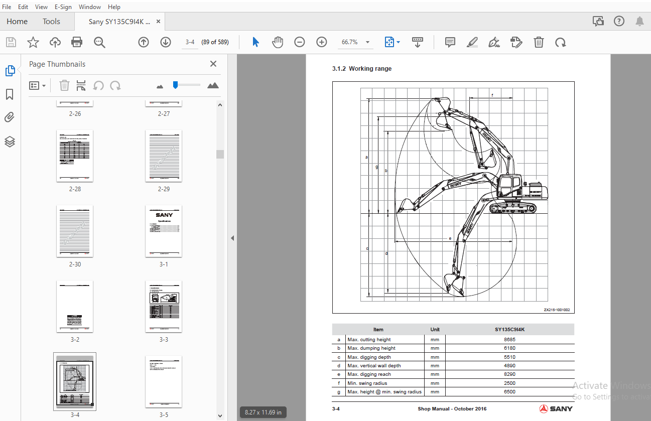
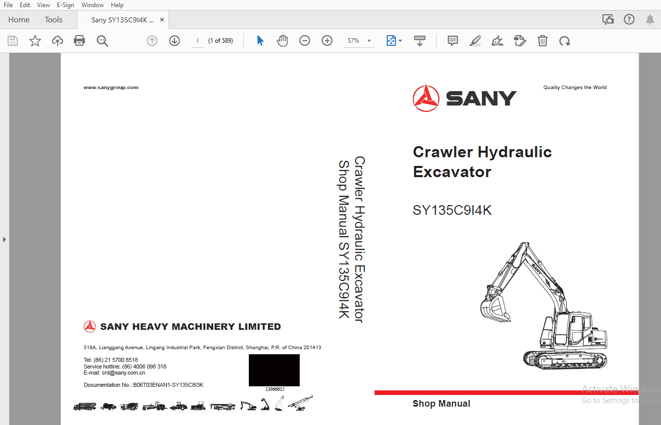
TABLE OF CONTENTS:
Sany SY135C9I4K Crawler Hydraulic Excavator Service Manual – PDF DOWNLOAD
1 Introduction
1 1 How to Read the Shop Manual 1-3
1 2 Terms for Maintenance Standard 1-5
1 3 Handling Electrical and Hydraulic Components 1-7
1 3 1 Points to remember when handling electric components 1-7
1 3 2 Points to remember when handling hydraulic equipment 1-16
1 4 Hose Connector 1-18
1 4 1 Type of hose connector 1-19
1 4 2 Hose connector tightening torque table 1-19
1 4 3 Connection of O-rings 1-20
1 5 Table of Standard Tightening Torques 1-21
1 6 Type of Bolts 1-22
1 7 Tightening Sequence 1-22
1 8 Maintenance of Half Flanges 1-23
1 8 1 Table of tightening torques for half f ange bolts 1-23
1 9 Conversion Table 1-24
2 Shop Safety
2 1 Hazard Alert Information 2-3
2 2 General Shop Safety 2-6
2 2 1 Rules and shop behavior 2-7
2 2 2 Housekeeping 2-7
2 2 3 Shop Liquids Storage 2-8
2 2 4 Cleaning Parts 2-8
2 2 5 Jacking Up the Machine 2-9
2 2 6 Electrical Dangers 2-9
2 2 7 Removing Attachments 2-10
2 2 8 Cleaning the Machine 2-10
2 2 9 Using the Correct Tools 2-10
2 2 10 Hoisting a Load 2-11
2 2 11 Appropriate Working Apparel 2-12
2 2 12 Safety Partners 2-12
2 2 13 Two people when engine running 2-13
2 2 14 Driving Pins 2-13
2 2 15 Aligning Parts or Components 2-14
2 2 16 Fire Extinguisher and Emergency Exits 2-14
2 2 17 Personal Protective Equipment 2-14
2 2 18 Running the Machine 2-15
2 2 19 Accumulator 2-16
2 2 20 Adding Fluids to a System 2-16
2 2 21 Track Recoil Springs 2-17
2 2 22 High-Pressure Fluid Lines 2-17
2 2 23 Safe Work Preparations 2-18
2 2 24 Mounting and Dismounting 2-19
2 2 25 Battery Hazards 2-20
2 2 26 Jump-Start Safety 2-21
2 2 27 Disconnecting the System Power 2-21
2 2 28 Lockout/tagout 2-22
2 2 29 Sequence of Procedures 2-22
2 2 30 Chemical hazard 2-24
2 2 31 Material Safety Data Sheets (MSDS) 2-24
2 3 Precautions for sling work and giving signals 2-25
3 Specifi cations
3 1 Overall Assembly Drawing 3-3
3 1 1 Dimension drawing 3-3
3 1 2 Working range 3-4
3 2 Engine Performance Curve 3-5
3 3 Technical Specif cations 3-6
3 4 Weight table 3-7
3 5 Lubricant, Fuel and Coolant 3-8
4 Structure, Function
4 1 Damping and Power Transmission system 4-5
4 2 Cooling System 4-6
4 3 Power Train 4-8
4 4 Swing Bearing 4-9
4 5 Swing Machinery 4-10
4 6 Track Frame 4-12
4 7 Tensioning device 4-14
4 8 Sprocket 4-15
4 9 Idler 4-16
4 10 Carrier Roller 4-18
4 11 Track Roller 4-19
4 12 Track shoe 4-20
4 13 Triple grouser shoe 4-23
4 14 Hydraulic System Layout 4-24
4 15 Control System 4-26
4 16 Hydraulic Tank and Filter 4-28
4 17 Hydraulic Pump 4-29
4 17 1 Pilot pump 4-35
4 17 2 Adjustor (KR36-9P0H) 4-36
4 17 2 1 Function 4-39
4 17 2 2 Controller makeup 4-39
4 17 2 3 Adjustment of the regulator 4-41
4 17 2 4 Power input 4-43
4 17 2 5 Adjustment of f ow control features 4-43
4 17 2 6 Power control (in an emergency) 4-45
4 17 2 8 Power change control (reducing power control) 4-48
4 17 2 7 Priority mechanism of small inclination (small f ow) command 4-48
4 18 Control valve 4-50
4 18 1 Control valve ports 4-50
4 18 2 Hydraulic Circuit Diagram 4-55
4 18 3 When in neutral position 4-56
4 18 4 Valve Spool Operation 4-59
4 18 4 1 Boom 4-59
4 18 4 2 Arm 4-61
4 18 4 3 Bucket 4-63
4 18 4 4 Travel 4-65
4 18 4 5 Swing 4-66
4 18 4 6 Dozer blade 4-67
4 18 5 Relief valve operation principle 4-69
4 18 5 1 Main relief valve 4-69
4 18 5 2 Port relief valve 4-71
4 18 6 Lock valve operation principle 4-74
4 18 7 Drawings 4-78
4 18 7 1 Sectional view 4-78
4 18 7 2 Straight travel, left travel (C-C) 4-81
4 18 7 3 Right travel, swing (D-D) 4-82
4 18 7 4 Bucket, boom raise conf uence (E-E) 4-83
4 18 7 5 Boom, arm (F-F) 4-84
4 18 7 6 Section view (G-G) 4-85
4 18 7 7 Arm conf uence 2 (L-L) 4-86
4 18 7 8 Section view (H-H,K-K) 4-87
4 19 Center swivel joint 4-88
4 20 Travel motor (Final drive) 4-90
4 20 1 Outline 4-93
4 20 1 1 Travel speed selection 4-93
4 20 2 Operation 4-94
4 20 2 1 Motor operation 4-94
4 20 2 2 Brake valve operation 4-96
4 20 2 3 Counterbalance valve and check valve 4-96
4 20 2 4 Safety valve 4-98
4 20 2 5 Parking brake operation 4-100
4 21 Swing Motor 4-101
4 21 1 Swing holding brake 4-103
4 21 2 Relief valve portion 4-105
4 21 2 2 Structure 4-105
4 21 2 3 Function 4-105
4 21 2 1 Operation 4-105
4 21 3 Reverse prevention valve 4-107
4 21 3 1 Operation drawing 4-107
4 21 3 2 Drawing of effects 4-108
4 21 3 3 Outline 4-108
4 21 3 4 Operation 4-109
4 22 Solenoid Valve 4-115
4 23 PPC Accumulator 4-117
4 24 Pilot Oil Filter 4-118
4 25 PPC valve 4-119
4 25 1 For swing and work equipment 4-119
4 25 2 Travel 4-123
4 26 Hydraulic Cylinder 4-127
4 26 1 Boom cylinder 4-127
4 26 2 Arm cylinder 4-127
4 26 3 Bucket cylinder 4-127
4 26 4 Dozer blade cylinder 4-128
4 27 Work Equipment 4-129
4 27 1 Dimensions 4-129
4 28 Air Conditioning System 4-135
4 28 1 A/C Components Layout Drawing 4-137
4 28 2 Control panel 4-138
4 28 3 Electrical Circuit Diagram 4-139
4 28 4 Refrigeration principle 4-141
4 28 4 1 Refrigeration cycle diagram 4-141
4 28 4 2 Heating cycle diagram 4-141
4 28 5 Compressor 4-142
4 28 6 Clutch 4-144
4 28 7 Condenser 4-145
4 28 8 Expansion valve 4-145
4 28 9 Evaporator 4-146
4 28 10 Receiver tank 4-146
4 28 11 Pressure switch 4-147
4 28 12 Pressure switch 4-148
4 28 13 Fresh air sensor 4-149
4 28 14 Refrigerant 4-149
4 28 15 Compressor oil 4-168
4 29 Engine Control 4-169
4 29 1 Engine control system diagram 4-169
4 29 2 System operation 4-170
4 29 3 Components 4-171
4 29 3 1 Fuel control dial 4-171
4 29 3 2 Engine controller 4-173
4 29 3 3 Input and output port 4-174
4 30 Electrical Control System 4-175
4 30 1 Control function 4-175
4 30 2 Control system diagram 4-176
4 30 3 Engine and pump composite control function 4-178
4 30 4 Pump control function 4-182
4 30 4 1 Straight travel control 4-184
4 30 5 Duo travel speed control 4-185
4 30 6 Engine preheating and overheating alarm 4-187
4 30 7 Engine oil underpressure alarm 4-189
4 30 8 Auto idle function 4-190
4 30 9 Auto acceleration control 4-191
4 30 10 Engine speed calibration control 4-191
4 30 11 System components 4-192
4 30 11 1 Sensor 4-192
4 31 Monitor System 4-196
4 31 1 Machine monitor 4-197
4 31 2 Monitor functions 4-198
4 31 3 Monitor operation 4-201
5 Standard Values
5 1 Standard Values for Engine-related Parts 5-3
5 2 Standard Values for Chassis-related Parts 5-4
6 Testing and Adjusting
6 1 Exhaust Gas Color – Test 6-3
6 2 Valve Clearance – Adjust 6-5
6 2 1 Testing 6-5
6 2 2 Adjusting 6-6
6 3 Compression Pressure – Measure 6-7
6 4 Engine Oil Pressure – Measure 6-9
6 5 Engine Speed Sensor – Adjust 6-10
6 6 Fan Belt Tension- Test and Adjust 6-11
6 6 1 Test 6-11
6 6 2 Adjust 6-11
6 7 A/C Compressor Belt Tension – Test and Adjust 6-12
6 7 1 Test 6-12
6 7 2 Adjust 6-12
6 8 Swing Bearing Clearance – Measure 6-13
6 9 Track tension – Test and Adjust 6-15
6 9 1 Test 6-15
6 9 2 Adjust 6-15
6 10 Oil Pressure in Work Equipment, Swing and Travel Circuit – Test and Adjust 6-17
6 10 1 Measure 6-17
6 10 2 Adjust 6-19
6 11 Control Circuit Oil Pressure – Test and Adjust 6-22
6 11 1 Measure 6-22
6 12 Solenoid Valve Output Pressure – Measure 6-23
6 13 PPC Valve Output Pressure – Measure 6-26
6 14 Work Equipment and Swing PPC Valve Play – Adjust 6-29
6 15 Work Equipment Hydraulic Drift – Test 6-30
6 16 Residual Pressure in Hydraulic Circuit – Release 6-33
6 17 Oil Leakage – Measure 6-35
6 18 Air in Each Component – Bleed 6-39
7 Troubleshooting
7 1 Points to Remember when Troubleshooting 7-3
7 2 Checks before Troubleshooting 7-5
7 3 Classif cation and Procedures for Troubleshooting 7-6
7 3 1 Classif cation of troubleshooting 7-6
7 3 2 Procedures for troubleshooting 7-6
7 4 Failure Symptoms and Troubleshooting Codes 7-8
7 5 Connector Location and Electrical Circuit Diagram 7-10
7 5 1 Table of connectors 7-10
7 5 2 Connector location layout 7-14
7 5 3 SWP type connector 7-19
7 5 4 A/AMP type connector 7-20
7 5 5 DT type connector 7-21
7 6 Troubleshooting of Electrical System (E – Mode) 7-22
7 7 Troubleshooting of Hydraulic and Mechanical System (H – Mode) 7-48
8 Disassembly and Assembly
8 1 How to Read This Manual 8-5
8 1 1 Removing and Installing an Assembly 8-5
8 1 2 Disassembling and assembling an assembly 8-5
8 1 3 Special tools 8-5
8 1 4 The symbols used in this section 8-6
8 2 Operating Precautions 8-7
8 3 Track AS – Remove and Install 8-10
8 3 1 Removal 8-10
8 3 2 Installation 8-11
8 4 Dozer Blade AS – Remove and Install 8-12
8 4 1 Remove 8-12
8 3 喷油泵总成的拆卸和安装 8-10
8 4 气缸盖总成的拆卸和安装拆卸 8-26
8 5 散热器总成的拆卸和安装拆卸 8-52
8 7 发动机和液压泵总成的拆卸和安装 8-54
8 4 2 Install 8-13
8 5 Sprocket – Remove and Install 8-14
8 5 1 Removal 8-14
8 5 2 Installation 8-14
8 6 Final Drive AS – Remove and Install 8-15
8 6 1 Removal 8-15
8 6 2 Installation 8-16
8 7 Idler AS – Disassemble and Assemble 8-17
8 7 1 Disassemble 8-17
8 7 2 Assemble 8-18
8 8 Tension Spring – Disassemble and Assemble 8-21
8 8 1 Removal 8-21
8 8 2 Assemble 8-23
8 9 Track Roller Assembly – Disassemble and Assemble 8-25
8 9 1 Disassemble 8-25
8 9 2 Assemble 8-25
8 10 Carrier Roller Assembly – Disassemble and Assemble 8-26
8 10 1 Disassemble 8-26
8 10 2 Assemble 8-26
8 11 Swing Motor and Swing Drive AS – Remove and Install 8-27
8 11 1 Removal 8-27
8 11 2 Installation 8-28
8 12 Swing Motor and Swing Drive AS – Disassemble and Assemble 8-29
8 12 1 Disassembly 8-29
8 12 2 Assembly 8-34
8 13 Swivel Joint AS – Remove and Install 8-39
8 13 1 Removal 8-39
8 13 2 Installation 8-40
8 14 Swivel Joint AS – Disassemble and Assemble 8-41
8 14 1 Disassemble 8-41
8 14 2 Assemble 8-42
8 15 Work Equipment AS – Remove and Install 8-43
8 15 1 Removal 8-43
8 15 2 Installation 8-44
8 16 Swing Platform AS – Remove and Install 8-46
8 16 1 Removal 8-46
8 16 2 Installation 8-48
8 17 Swing Bearing AS – Remove and Install 8-49
8 17 1 Removal 8-49
8 17 2 Installation 8-50
8 18 Hydraulic Tank AS – Remove and Install 8-51
8 18 1 Removal 8-51
8 18 2 Installation 8-53
8 19 Control Valve AS – Remove and Install 8-54
8 19 1 Removal 8-54
8 19 2 Installation 8-56
8 20 Hydraulic Pump AS – Remove and Install 8-57
8 20 1 Removal 8-57
8 20 2 Installation 8-60
8 21 Oil Seal (Hydraulic Pump Input Shaft)- Remove and Install 8-61
8 21 1 Removal 8-61
8 21 2 Installation 8-61
8 22 PPC Valve AS (Work Equipment) – Disassemble and Assemble 8-62
8 22 1 Assemble 8-62
8 23 PPC Valve AS (Travel) – Disassemble and Assemble 8-64
8 23 1 Assemble 8-64
8 24 Hydraulic Cylinder AS – Disassemble and Assemble 8-65
8 24 1 Disassembly 8-66
8 24 2 Assembly 8-71
8 25 Counterweight AS – Remove and Install 8-76
8 25 1 Removal 8-76
8 25 2 Installation 8-77
8 26 Air Conditioner AS – Remove and Install 8-78
8 26 1 Removal 8-78
8 26 2 Installation 8-82
8 27 Cab AS – Remove and Install 8-83
8 27 1 Removal 8-83
8 27 2 Installation 8-87
8 28 Cab Window Glass – Disassemble and Assemble 8-88
8 28 1 Removal 8-89
8 28 2 Installation 8-93
8 29 Front Window AS – Disassemble and Assemble 8-106
8 29 1 Disassemble 8-106
8 29 2 Assemble 8-109
8 30 Monitor – Remove and Install 8-114
8 30 1 Removal 8-114
8 30 2 Installation 8-114
8 31 Controller AS – Remove and Install 8-115
8 31 1 Removal 8-115
8 31 2 Installation 8-115
8 32 Radio 8-116
8 32 1 Structure 8-116
8 32 2 Removal 8-117
8 32 3 Installation 8-118
8 32 4 Connector model and wiring 8-118
8 33 Battery 8-119
8 33 1 Structure 8-119
8 33 2 Removal 8-120
8 33 3 Installation 8-121
8 33 4 Replacement 8-121
8 34 Start Switch 8-122
8 34 1 Structure 8-122
8 34 2 Removal 8-123
8 35 Fuse Box 8-125
8 35 1 Removal 8-125
8 36 Wiper 8-126
8 36 1 Structure 8-126
8 36 2 Working principle 8-126
8 36 3 Removal 8-127
8 36 5 Installation 8-128
8 36 4 Angle adjustment of wiper arm 8-128
8 37 Relay 8-129
8 37 1 Engine relay 8-129
8 37 2 Other relays 8-130
8 38 Sensor 8-132
8 39 Connector Terminals – Insert and Remove 8-134
8 39 1 Insertion 8-134
8 39 2 Removal 8-135
9 System Schematics
9 1 Hydraulic Circuit Diagram 9-3
9 2 Electrical System Diagram 9-4
9 3 Air Conditioner Circuit Diagram 9-5
9 4 Control Switches Harness 9-6
9 5 Cab Harness 9-7
9 6 Chassis Harness 9-8
More products