$39
Sany SY16C Crawler Hydraulic Excavator Service Manual – PDF DOWNLOAD
Sany SY16C Crawler Hydraulic Excavator Service Manual – PDF DOWNLOAD
FILE DETAILS:
Sany SY16C Crawler Hydraulic Excavator Service Manual – PDF DOWNLOAD
Language : English
Pages : 454
Downloadable : Yes
File Type : PDF
IMAGES PREVIEW OF THE MANUAL:
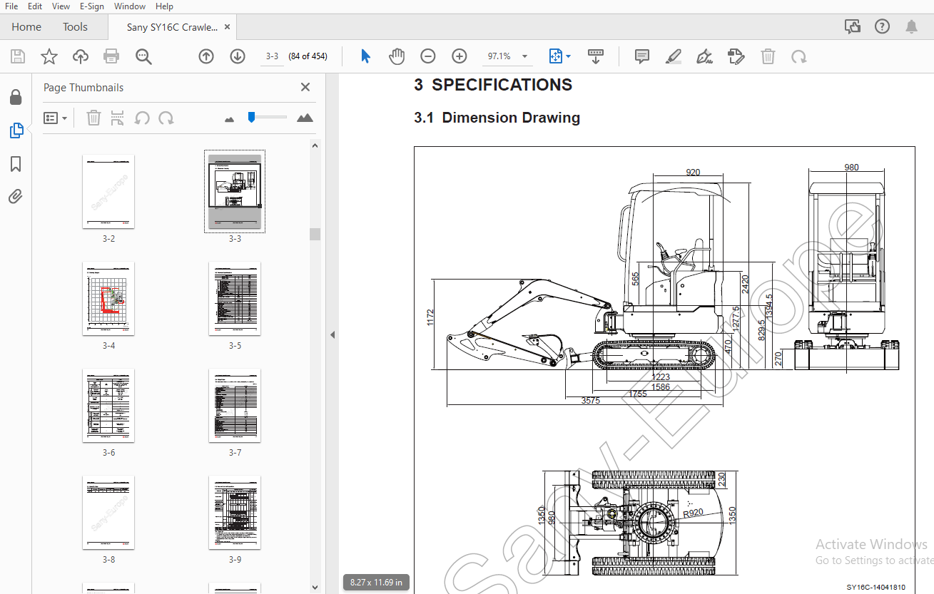
TABLE OF CONTENTS:
Sany SY16C Crawler Hydraulic Excavator Service Manual – PDF DOWNLOAD
1 Introduction
1 1 How to Read the Manual 1-3
1 1 1 Shop manual organization 1-3
1 1 3 Symbols 1-4
1 1 4 Units 1-4
1 1 2 Revision and distribution 1-4
1 2 Technical Terms 1-5
1 2 1 Standard size and tolerance 1-5
1 2 2 Standard clearance and value 1-6
1 2 3 Standard interference 1-6
1 2 4 Repair limit and allowable value 1-6
1 2 5 Clearance limit 1-6
1 2 6 Interference limit 1-7
1 3 Handling Electrical and Hydraulic Components 1-8
1 3 1 Points to remember when handling electric components 1-8
1 3 1 1 Handling wiring harnesses and connectors 1-8
1 3 1 2 Main failures occurring in wiring harness 1-9
1 3 1 3 Removing, installing, and drying connectors and wiring harnesses 1-11
1 3 1 4 Handling the integrated control monitor 1-15
1 3 1 5 Electric circuits troubleshooting precautions 1-16
1 3 2 Points to remember when handling hydraulic equipment 1-17
1 3 2 1 Be careful of the operating environment 1-17
1 3 2 2 Disassembly and maintenance work in the field 1-17
1 3 2 3 Sealing openings 1-17
1 3 2 4 Do not let any dirt or dust get in during refilling operations 1-18
1 3 2 5 Change hydraulic oil when the temperature is high 1-18
1 3 2 6 Flushing operations 1-18
1 3 2 7 Cleaning operations 1-19
1 4 Hose Connector 1-19
1 4 1 Type of hose connector 1-20
1 4 2 Hose connector tightening torque table 1-20
1 4 3 Connection of O-rings 1-21
1 5 Table of Standard Tightening Torques 1-22
1 6 Type of Bolts 1-23
1 7 Tightening Sequence 1-23
1 8 Maintenance of Half Flanges 1-24
1 8 1 Table of tightening torques for half flange bolts 1-24
1 8 2 Temperature 1-30
2 Shop Safety
2 1 Hazard Alert Information 2-3
2 2 General Shop Safety 2-5
2 2 1 Rules and shop behavior 2-6
2 2 2 Housekeeping 2-6
2 2 3 Shop Liquids Storage 2-7
2 2 4 Cleaning the Parts 2-7
2 2 5 Cleaning the Machine 2-8
2 2 6 Appropriate Working Apparel 2-8
2 2 7 Personal Protective Equipment 2-8
2 2 8 Using the Correct Tools 2-9
2 2 9 Fire Extinguisher and Emergency Exits 2-9
2 2 10 Electrical Dangers 2-10
2 2 11 Hoisting a Load 2-10
2 3 Before Repair 2-11
2 3 1 Safe Work Preparations 2-11
2 3 2 Preparing yourself 2-12
2 3 3 Lockout/Tagout 2-13
2 3 4 Two people when engine running 2-15
2 3 5 Safety Partners 2-15
2 4 Repair Precautions 2-16
2 4 1 Running the Machine 2-16
2 4 2 Mounting and Dismounting 2-17
2 4 3 Removing Attachments 2-18
2 4 4 Jacking Up the Machine 2-18
2 4 5 Adding Fluids to a System 2-18
2 4 6 Aligning Parts or Components 2-19
2 4 7 Driving Pins 2-19
2 4 8 When compressed air is used 2-19
2 4 9 Welding operation 2-20
2 4 10 Track Recoil Springs 2-20
2 4 11 High-Pressure Fluid Lines 2-21
2 4 12 Air-conditioning system maintenance 2-22
2 4 13 High voltage precautions 2-22
2 4 14 Disconnecting the System Power 2-23
2 4 15 Accumulator 2-23
2 4 17 Battery Hazards 2-24
2 4 18 Jump-Start Safety 2-25
2 4 19 Avoiding fire and explosion 2-26
2 4 20 Chemical hazard 2-27
2 4 21 Material Safety Data Sheets (MSDS) 2-27
2 4 22 Proper disposal of wastes 2-28
2 5 Other Precautions 2-29
2 5 1 Sling work and giving signals 2-29
2 5 2 Using mobile crane 2-31
2 5 3 Using overhead hoist crane 2-31
2 5 4 Selecting wire ropes 2-32
3 Specifications
3 1 Dimension Drawing 3-3
3 2 Working Ranges 3-4
3 3 Technical Specifications 3-5
3 4 Weight Table 3-7
3 5 Capacity Table 3-8
3 6 Fuel and Coolant Capacities 3-9
3 7 Engine Performance Curve 3-10
4 Structure and Functions
4 1 Engine and Cooling System 4-3
4 1 1 Water cooler and oil cooler 4-3
4 1 2 PTO (coupling) 4-4
4 1 3 Engine control device 4-5
4 2 Power Train 4-6
4 2 1 Power transmission system 4-6
4 2 2 Swing bearing 4-7
4 2 3 Swing drive 4-8
4 3 Undercarriage 4-9
4 3 1 Track frame 4-9
4 3 2 Tensioning device 4-10
4 4 Hydraulic System 4-11
4 4 1 Hydraulic lines 4-11
4 4 2 Hydraulic tank 4-12
4 4 3 Hydraulic pump 4-13
4 4 4 Control valve 4-23
4 4 5 Main valve section view 4-25
4 4 6 Load sensitive system 4-26
4 4 6 1 Basic principle 4-27
4 4 6 2 Operation and parameter of each function 4-29
4 4 6 3 Operation of the whole system 4-40
4 4 7 Swing motor 4-50
4 4 8 Safety valve 4-54
4 4 9 Central swivel joint 4-56
4 4 10 Travel motor 4-57
4 4 10 1 Working process of parking brake 4-60
4 4 10 2 Working process of brake valve 4-61
4 4 11 Control system 4-63
4 4 12 Work equipment and swing pilot valve 4-64
4 4 13 Travel pilot valve 4-69
4 4 14 Solenoid directional valve 4-73
4 4 15 Oil source control valve 4-74
4 4 16 Hydraulic cylinders 4-75
4 5 Electrical System 4-76
4 5 1 Electrical system layout (1/2) 4-76
4 5 2 Electrical system layout (2/2) 4-77
4 5 3 Electrical circuit diagram 4-78
4 6 Electronic Control System 4-79
4 6 1 System diagram 4-79
4 6 2 Electrical control system function 4-80
4 6 3 Engine control function 4-81
4 6 4 Valve control function 4-82
4 6 5 Manual preheating and overheating protection function 4-83
4 6 6 Travel control function 4-84
4 6 7 Monitoring system 4-85
4 7 Integrated controller 4-87
4 7 1 Monitor 4-87
4 7 2 Ports of integrated instrument 4-88
4 7 3 Electrical circuit diagram 4-89
4 7 4 Functional definition 4-90
5 Standard Values
5 1 Standard Values for Engine-Related Parts 5-3
5 2 Standard Values for Chassis-Related Parts 5-4
5 3 Standard Values for Electrical Parts 5-11
6 Testing and Adjusting
6 1 Engine Speed – Test 6-4
6 2 Exhaust Gas Color – Test 6-5
6 2 1 Using a hand tester 6-5
6 2 2 Using an instrument 6-5
6 3 Valve Clearance – Check and Adjust 6-7
6 4 Compression Pressure – Test 6-9
6 5 Injection Timing – Test and Adjust 6-10
6 5 1 Checking fuel injection timing 6-10
6 5 2 Adjusting the fuel injection timing 6-13
6 6 Oil Pressure – Test 6-14
6 7 Alternator Belt Tension – Test and Adjust 6-14
6 7 1 Testing 6-14
6 7 2 Adjusting 6-14
6 8 Fuel Control Lever – Adjust 6-15
6 9 Hydraulic Pressure in Oil Circuits – Test and Adjust 6-16
6 9 1 Testing 6-16
6 9 2 Adjusting main relief valve pressure 6-17
6 10 LS Differential Pressure and LS Valve – Test/Adjust 6-18
6 10 1 Testing with the similar pressure gauges 6-18
6 10 2 Adjusting LS valve 6-19
6 11 Hydraulic Pressure in Control Circuit – Test 6-20
6 12 Pilot Valve Output Pressure – Test 6-21
6 13 Work Equipment and Swing Pilot Valve – Adjust 6-22
6 14 Travel Deviation – Test 6-23
6 15 Oil Leakage – Test 6-24
6 15 1 Work equipment cylinder 6-24
6 15 2 Swing motor 6-26
6 15 3 Travel motor 6-26
6 16 Residual Pressure in Hydraulic Circuit – Release 6-27
6 17 Swing Bearing Clearance – Check 6-28
6 18 Track Tension – Check and Adjust 6-29
6 18 1 Checking track tension 6-29
6 18 2 Adjusting track tension 6-30
6 18 2 1 When the tension is high 6-30
6 18 2 2 When the tension is low 6-30
6 19 Air Purging 6-31
6 19 1 Hydraulic Pump 6-31
6 19 2 Hydraulic cylinder 6-32
6 19 3 Swing motor 6-32
6 19 4 Travel motor 6-33
7 Troubleshooting
7 1 Troubleshooting Precautions 7-5
7 2 Checks Before Troubleshooting 7-7
7 3 Connector Locations and System Diagrams 7-8
7 4 Number of Pins Required for Connection 7-11
7 5 Electric Wire Specifications 7-18
7 5 1 Type, Symbol and Material 7-18
7 5 2 Dimensions 7-19
7 6 How to Use the Judgement Chart 7-20
7 7 How to Use a Schematic Diagram for Troubleshooting 7-22
7 8 Troubleshooting the Electrical System 7-23
7 8 1 The whole machine does not react 7-23
7 8 2 Unable to shift travel speed 7-24
7 8 3 Engine does not start 7-25
7 8 4 Unable to stop the engine 7-26
7 9 Troubleshooting the Engine 7-27
7 9 1 How to use the chart of troubleshooting 7-27
7 9 2 Poor starting performance 7-33
7 9 3 Engine fails to start 7-36
7 9 3 1 Engine fails to rotate 7-36
7 9 3 2 The engine rotates but produce smoke 7-37
7 9 3 3 Fume is seen but the engine does not start 7-38
7 9 4 Engine acceleration is instable 7-39
7 9 5 Engine stops during operation 7-40
7 9 6 Engine rotates unstably (vibrates) 7-41
7 9 7 Low power output (lack of power) 7-42
7 9 8 Black exhaust gas (incomplete combustion) 7-43
7 9 9 Engine oil consumed excessively or exhaust gas turned blue 7-44
7 9 10 Engine oil is contaminated quickly 7-45
7 9 11 Fuel consumption is excessive 7-46
7 9 12 Coolant contains engine oil, water sprays back or water level drops 7-47
7 9 13 Engine oil pressure alert indicator lights up 7-48
7 9 14 Higher oil level 7-49
7 9 15 Higher coolant temperature (overheated) 7-50
7 9 16 Abnormal noise 7-51
7 9 17 Violent vibration 7-53
7 10 Troubleshooting the Hydraulic and Mechanical System 7-54
7 10 1 Work equipment, swing drive and final drive move slowly or is weak 7-54
7 10 2 Engine speed drops sharply or engine stalls 7-56
7 10 3 Work equipment, final drive and swing drive do not work 7-57
7 10 4 Abnormal noise occurs (around the pump) 7-57
7 10 5 Poor precise control performance or bad sensitivity 7-58
7 10 6 Boom moves slowly or power is weak 7-58
7 10 7 Arm moves slowly or power is weak 7-60
7 10 8 Bucket moves slowly or power is weak 7-62
7 10 9 Work equipment does not work (but travel and swing are normal) 7-63
7 10 10 Excessive hydraulic drift (of boom, arm and bucket) 7-63
7 10 11 Work equipment with greater load moves slowly in combined operation 7-64
7 10 12 Boom raises slowly during swing + boom UP operation 7-65
7 10 13 Travel speed drops considerably during travel + swing operation 7-65
7 10 14 Machine cannot make a straight travel 7-66
7 10 15 Travel deviation is big at beginning 7-68
7 10 16 Travel speed is low or power is weak 7-68
7 10 17 It Is difficult to change direction 7-69
7 10 18 Travel speed cannot be changed 7-70
7 10 19 Travel system fails (only at one side) 7-70
7 10 20 Swing operation fails 7-71
7 10 21 Poor swing acceleration 7-72
7 10 22 Excessive overrunning upon swing stoppage 7-74
7 10 23 Considerable shaking resulted from swing stoppage 7-75
7 10 24 Abnormally high noise resulted from swing stoppage 7-75
7 10 25 Excessive hydraulic drift of swing 7-76
7 10 26 Swing speed is faster than specified 7-76
7 10 27 Dozer blade moves slowly or power is weak 7-77
7 10 28 Dozer blade does not work 7-77
7 10 29 Excessive hydraulic drift of dozer blade 7-78
7 10 30 Unable to expand and contract rubber tracks 7-78
7 11 Troubleshooting the Machine Monitoring System 7-79
7 11 1 Harness of machine monitoring system 7-79
7 11 2 Engine coolant temperature reading abnormal 7-80
7 11 3 Work lamps do not light up 7-81
7 11 4 Horn does not sound 7-82
8 Disassembly and Assembly
8 1 Operating Precautions 8-7
8 2 Engine and Main Pump AS 8-10
8 2 1 Removal 8-10
8 2 2 Installation 8-13
8 3 Center Swivel Joint AS 8-14
8 3 1 Removal 8-14
8 3 2 Installation 8-15
8 3 3 Disassembly 8-16
8 3 4 Assembly 8-16
8 4 Sprocket 8-17
8 4 1 Removal 8-17
8 4 2 Installation 8-17
8 5 Travel Motor AS 8-18
8 5 1 Removal 8-18
8 5 2 Installation 8-19
8 5 3 Sectional view 8-20
8 5 4 Exploded view of reducer 8-22
8 5 5 Exploded view of reducer AS 8-23
8 5 6 Exploded view of the hydraulic motor AS 8-24
8 5 7 Parts catalogue 8-25
8 5 8 Disassembly 8-27
8 5 8 1 Preparatory work 8-27
8 5 8 2 General precautions during work 8-27
8 5 8 3 Disassembling procedure 8-28
8 5 9 Table of maintenance standard 8-38
8 5 10 Assembly 8-41
8 5 10 1 Preparatory work 8-41
8 5 10 2 General precautions 8-41
8 5 10 3 Assembly procedure 8-42
8 5 10 4 Quality assurance 8-56
8 6 Swing Motor and Swing Mechanism AS 8-57
8 6 1 Removal 8-57
8 6 2 Installation 8-57
8 7 Swing Motor AS 8-58
8 7 1 Disassembly 8-58
8 7 2 Reassembly 8-61
8 8 Swing Platform AS 8-62
8 8 1 Removal 8-62
8 8 2 Installation 8-63
8 9 Swing Bearing AS 8-64
8 9 1 Removal 8-64
8 9 2 Installation 8-64
8 10 Idler and Tension Spring AS 8-65
8 10 1 Removal 8-65
8 10 2 Installation 8-65
8 11 Tension Spring AS 8-66
8 11 1 Disassembly 8-66
8 11 2 Assembly 8-67
8 12 Idler AS 8-68
8 12 1 Disassembly 8-68
8 11 3 Assembly 8-68
8 13 Track Roller AS 8-69
8 13 1 Removal 8-69
8 13 2 Installation 8-69
8 13 3 Disassemble 8-70
8 13 4 Assembly 8-70
8 14 Rubber Tracks 8-71
8 14 1 Removal 8-71
8 14 2 Installation 8-71
8 15 Hydraulic Tank AS 8-72
8 15 1 Removal 8-72
8 15 2 Installation 8-72
8 16 Main Pump AS 8-73
8 16 1 Removal 8-73
8 15 3 Installation 8-73
8 17 Main Pump Input Shaft Oil Seal 8-74
8 17 1 Removal 8-74
8 17 2 Installation 8-74
8 18 Control Valve AS 8-75
8 18 1 Removal 8-75
8 18 2 Installation 8-75
8 19 Manual Directional Valve 8-76
8 19 1 Removal 8-76
8 19 2 Installation 8-76
8 20 Oil Source Control Valve AS 8-76
8 20 1 Removal 8-76
8 20 2 Installation 8-76
8 21 Left Pilot Valve AS (Arm and Swing Control) 8-77
8 21 1 Removal 8-77
8 21 2 Installation 8-77
8 22 Right Pilot Valve (Boom and Bucket Control) 8-78
8 22 1 Removal 8-78
8 22 2 Installation 8-78
8 23 Work Equipment Pilot Valve AS 8-79
8 23 1 Disassembly 8-79
8 23 2 Assembly 8-79
8 24 Travel Pilot Valve AS 8-81
8 24 1 Removal 8-81
8 24 2 Installation 8-81
8 24 3 Disassembly 8-82
8 24 4 Assembly 8-82
8 25 Boom Cylinder AS 8-83
8 25 1 Removal 8-83
8 25 2 Installation 8-84
8 26 Arm Cylinder AS 8-85
8 26 1 Removal 8-85
8 26 2 Installation 8-86
8 27 Bucket Cylinder AS 8-87
8 27 1 Removal 8-87
8 27 2 Installation 8-88
8 28 Deflection Cylinder AS 8-89
8 28 1 Removal 8-89
8 28 2 Installation 8-89
8 29 Dozer Blade Cylinder AS 8-90
8 29 1 Removal 8-90
8 28 3 Installation 8-90
8 30 Hydraulic Cylinder AS 8-91
8 30 1 Disassembly 8-91
8 30 2 Assembly 8-94
8 31 Work Equipment AS 8-97
8 31 1 Removal 8-97
8 31 2 Installation 8-98
8 32 Bucket and Arm AS 8-99
8 32 1 Removal 8-99
8 32 2 Installation 8-100
8 33 Bucket AS 8-101
8 33 1 Removal 8-101
8 33 2 Installation 8-102
8 34 Arm AS 8-103
8 34 1 Removal 8-103
8 34 2 Installation 8-104
8 35 Boom AS 8-105
8 35 1 Removal 8-105
8 35 2 Installation 8-106
8 36 Boom Deflection Joint AS 8-107
8 36 1 Removal 8-107
8 36 2 Installation 8-107
8 37 Dozer Blade AS 8-108
8 37 1 Removal 8-108
8 37 2 Installation 8-109
8 38 Canopy AS 8-110
8 38 1 Removal 8-110
8 38 2 Installation 8-110
8 39 Counterweight AS 8-111
8 39 1 Removal 8-111
8 39 2 Installation 8-111
8 40 Monitor AS 8-112
8 40 1 Removal 8-112
8 40 2 Installation 8-112
9 Maintenance Standard
9 1 Swing Mechanism 9-3
9 2 Swing Bearing 9-4
9 3 Track Frame 9-5
9 4 Idler 9-6
9 5 Track Roller 9-7
9 6 Rubber track 9-9
9 7 Work Equipment 9-10
9 8 Arm Dimensions 9-12
9 9 Bucket Dimensions 9-13
9 10 Hydraulic Cylinder 9-14
10 System Schematics
10 1 Hydraulic Circuit Diagram 10-3
10 2 General System Diagram (1/5) 10-4
10 3 General System Diagram (2/5) 10-5
10 4 General System Diagram (3/5) 10-6
10 5 General System Diagram (4/5) 10-7
10 6 General System Diagram (5/5) 10-8
10 7 Electrical Circuit Diagram 10-9
More products