$40
Sany SY265C9C5K Crawler Hydraulic Excavator Service Manual – PDF DOWNLOAD
Sany SY265C9C5K Crawler Hydraulic Excavator Service Manual – PDF DOWNLOAD
FILE DETAILS:
Sany SY265C9C5K Crawler Hydraulic Excavator Service Manual – PDF DOWNLOAD
Language : English
Pages : 588
Downloadable : Yes
File Type : PDF
IMAGES PREVIEW OF THE MANUAL:
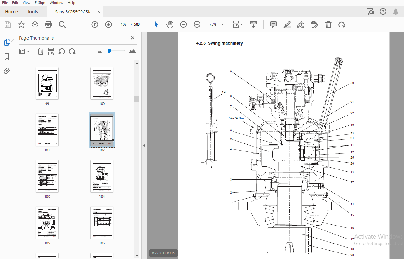
TABLE OF CONTENTS:
Sany SY265C9C5K Crawler Hydraulic Excavator Service Manual – PDF DOWNLOAD
“`
1 Introduction
1-1 How to Read the Manual
1-3 Shop manual organization
1-3 Revision and distribution
1-4 Symbols
1-5 Units
1-6 Technical Terms
1-6 Standard size and tolerance
1-7 Standard clearance and value
1-7 Standard interference
1-8 Repair limit and allowable value
1-8 Clearance limit
1-8 Interference limit
1-9 Handling Electrical and Hydraulic Components
1-9 Points to remember when handling electric components
1-9 Handling wiring harnesses and connectors
1-10 Main failures occurring in wiring harness
1-12 Removing, installing, and drying connectors and wiring harnesses
1-16 Handling the integrated control monitor
1-17 Electric circuits troubleshooting precautions
1-18 Points to remember when handling hydraulic equipment
1-18 Be careful of the operating environment
1-18 Disassembly and maintenance work in the field
1-18 Sealing openings
1-18 Do not let any dirt or dust get in during refilling operations
1-19 Change hydraulic oil when the temperature is high
1-19 Flushing operations
1-19 Cleaning operations
1-20 Hose Connector
1-21 Type of hose connector
1-21 Hose connector tightening torque table
1-22 Connection of O-rings
1-23 Table of Standard Tightening Torques
1-24 Type of Bolts
1-24 Tightening Sequence
1-25 Maintenance of Half Flanges
1-25 Table of tightening torques for half flange bolts
1-31 Temperature2 Shop Safety
2-3 Hazard Alert Information
2-5 General Shop Safety
2-6 Rules and shop behavior
2-6 Housekeeping
2-7 Shop Liquids Storage
2-7 Cleaning the Parts
2-8 Cleaning the Machine
2-8 Appropriate Working Apparel
2-8 Personal Protective Equipment
2-9 Using the Correct Tools
2-9 Fire Extinguisher and Emergency Exits
2-10 Electrical Dangers
2-10 Hoisting a Load
2-11 Before Repair
2-11 Safe Work Preparations
2-12 Preparing yourself
2-13 Lockout/Tagout
2-15 Two people when engine running
2-15 Safety Partners
2-16 Repair Precautions
2-16 Running the Machine
2-17 Mounting and Dismounting
2-18 Removing Attachments
2-18 Jacking Up the Machine
2-18 Adding Fluids to a System
2-19 Aligning Parts or Components
2-19 Driving Pins
2-19 When compressed air is used
2-20 Welding operation
2-20 Track Recoil Springs
2-21 High-Pressure Fluid Lines
2-22 Air-conditioning system maintenance
2-22 High voltage precautions
2-23 Disconnecting the System Power
2-23 Accumulator
2-24 Battery Hazards
2-25 Jump-Start Safety
2-26 Avoiding fire and explosion
2-27 Chemical hazard
2-27 Material Safety Data Sheets (MSDS)
2-28 Proper disposal of wastes
2-29 Other Precautions
2-29 Sling work and giving signals
2-31 Using mobile crane
2-31 Using overhead hoist crane
2-33 Selecting wire ropes3 Specifications
3-3 Dimensions
3-4 Working ranges
3-5 Technical Specifications
3-7 Table of Weights
3-8 Engine Oil, Fuel and Coolant
3-10 Engine Performance Curve4 Structure and Functions
4-5 Engine and Cooling System
4-5 Engine-related parts
4-6 Radiator and intercooler
4-7 Power Train
4-7 Power train
4-8 Travel reducer AS
4-10 Swing reduction mechanism
4-12 Swing bearing
4-14 Undercarriage
4-14 Track frame and tensioning mechanism
4-16 Idler
4-18 Carrier roller
4-19 Track roller
4-21 Tracks
4-25 Hydraulic System, Part 1
4-25 Deployment of hydraulic parts
4-26 Hydraulic Pump
4-28 Pilot pump
4-29 Regulator
4-44 Oil delivery control
4-45 Pilot pump
4-46 Regulator
4-58 Hydraulic System, Part 2
4-58 Control valve
4-60 Main valve structure
4-65 Hydraulic circuit (With bucket confluence function)
4-88 Hydraulic System, Part 3
4-88 Swing motor
4-91 Relief valve section
4-93 Anti-jerk valve
4-95 Central swivel joint
4-96 Travel motor
4-103 Operation of parking brake
4-104 Operation of braking valve
4-112 Control system
4-113 Pilot valve
4-117 Travel pilot valve
4-121 Solenoid valves
4-122 Pilot accumulator
4-123 Pilot oil filter
4-124 Work Equipment
4-124 Component dimensions
4-126 Arm dimensions
4-128 Bucket dimensions
4-130 Air Conditioning System
4-131 Layout of A/C components
4-132 A/C control panel
4-133 Diagram of electrical circuit
4-135 Refrigeration principle
4-136 Compressor
4-138 Clutch
4-139 Condenser
4-140 Expansion valve
4-140 Evaporator
4-141 Dehydrator
4-142 Pressure switch
4-143 Refrigerant
4-146 Evacuation
4-148 Refrigerant filling operation
4-153 Troubleshooting with manifold pressure gauge
4-162 Compressor oil
4-163 Engine Control
4-164 System operation
4-165 System components
4-165 Fuel control dial
4-166 Engine control unit (ECU)
4-170 Electrical Control System
4-170 Control function
4-171 Diagram of machine control system
4-173 Engine-pump combination control
4-176 Valve control function
4-177 Travel control function
4-178 Low engine oil pressure alarm and protection
4-179 High engine coolant temperature alarm and protection
4-180 Engine preheating control
4-181 Engine starting and energizing delay control
4-182 System parts and components
4-182 Pump pressure sensor
4-183 Pilot pressure sensor
4-184 Engine speed sensor
4-185 Coolant temperature sensor
4-186 Fuel level sensor
4-187 Oil pressure switch
4-188 Monitor System
4-189 Monitor
4-190 Monitor panel5 Standard Values
5-3 Standard Values for Engine-Related Parts
5-4 Standard Values for Chassis-Related Parts6 Testing and Adjusting
6-3 Exhaust Gas Color – Test
6-5 Valve Clearance – Adjust
6-8 Compression Force – Test
6-10 Fuel Injection Timing – Test and Adjust
6-11 Engine Oil Pressure – Test
6-12 Engine Speed Sensor – Adjust
6-13 A/C Compressor Belt Tension – Check and Adjust
6-14 Swing Bearing Clearance – Check
6-16 Track Tensioning device – Check and Adjust
6-18 Oil in hydraulic circuits – Test and Adjust
6-22 Control Oil Circuit Pressure – Check and Adjust
6-23 Solenoid Valve Output Pressure – Test
6-25 Pilot Valve Output Pressure – Test
6-26 Work Equipment and Swing PPC Valves – Adjust
6-27 Hydraulic Drift of Work Equipment – Test
6-29 Remaining Pressure in Hydraulic Lines – Relieve
6-30 Oil Leakage Amount – Test
6-34 Air in Each Component – Purge
More products