$41
Sany SY335C9C4K Crawler Hydraulic Excavator Service Manual – PDF DOWNLOAD
Sany SY335C9C4K Crawler Hydraulic Excavator Service Manual – PDF DOWNLOAD
FILE DETAILS:
Sany SY335C9C4K Crawler Hydraulic Excavator Service Manual – PDF DOWNLOAD
Language : English
Pages : 628
Downloadable : Yes
File Type : PDF
IMAGES PREVIEW OF THE MANUAL:
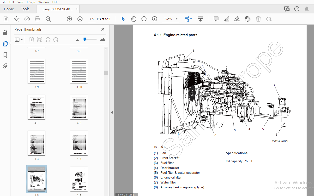
TABLE OF CONTENTS:
Sany SY335C9C4K Crawler Hydraulic Excavator Service Manual – PDF DOWNLOAD
1 Introduction
1 1 How to Read the Shop Manual 1-3
1 1 1 Organization of the shop manual 1-3
1 1 3 Symbols 1-4
1 1 4 Units 1-4
1 1 2 Revision and distribution 1-4
1 2 Terms for Maintenance Standard 1-5
1 2 1 Standard size and tolerance 1-5
1 2 2 Standard clearance and standard value 1-6
1 2 3 Standard interference 1-6
1 2 4 Repair limit and allowable value 1-6
1 2 5 Clearance limit 1-6
1 2 6 Interference limit 1-7
1 3 Handling Electrical and Hydraulic Components 1-8
1 3 1 Points to remember when handling electric components 1-8
1 3 1 1 Handling wiring harnesses and connectors 1-8
1 3 1 2 Main failures occurring in wiring harness 1-9
1 3 2 Points to remember when handling hydraulic equipment 1-17
1 4 Hose Connector 1-19
1 4 1 Type of hose connector 1-20
1 4 2 Hose connector tightening torque table 1-20
1 4 3 Connection of O-rings 1-21
1 5 Table of Standard Tightening Torques 1-22
1 6 Type of Bolts 1-23
1 7 Tightening Sequence 1-23
1 8 Maintenance of Half Flanges 1-24
1 8 1 Table of tightening torques for half fl ange bolts 1-24
1 9 Conversion Table 1-25
2 Shop Safety
2 1 Hazard Alert Information 2-3
2 2 General Shop Safety 2-4
2 2 1 Rules and shop behavior 2-5
2 2 2 Housekeeping 2-5
2 2 3 Shop Liquids Storage 2-6
2 2 4 Cleaning Parts 2-6
2 2 5 Jacking Up the Machine 2-7
2 2 6 Electrical Dangers 2-7
2 2 7 Removing Attachments 2-8
2 2 8 Cleaning the Machine 2-8
2 2 9 Using the Correct Tools 2-8
2 2 10 Hoisting a Load 2-9
2 2 11 Appropriate Working Apparel 2-10
2 2 12 Safety Partners 2-10
2 2 13 Two people when engine running 2-11
2 2 14 Driving Pins 2-11
2 2 15 Aligning Parts or Components 2-12
2 2 16 Fire Extinguisher and Emergency Exits 2-12
2 2 17 Personal Protective Equipment 2-12
2 2 18 Running the Machine 2-13
2 2 19 Accumulator 2-14
2 2 20 Adding Fluids to a System 2-14
2 2 21 Track Recoil Springs 2-15
2 2 22 High-Pressure Fluid Lines 2-15
2 2 23 Safe Work Preparations 2-16
2 2 24 Mounting and Dismounting 2-17
2 2 25 Battery Hazards 2-18
2 2 26 Jump-Start Safety 2-19
2 2 27 Disconnecting the System Power 2-19
2 2 28 LOCKOUT/TAGOUT 2-20
2 2 29 Sequence of Procedures 2-20
2 2 30 CHEMICAL HAZARDS 2-22
2 2 31 Material Safety Data Sheets (MSDS) 2-22
3 Specifi cations
3 1 Dimensions 3-3
3 2 Working Ranges 3-4
3 3 Technical Specifi cations 3-5
3 4 Weight Table 3-6
3 5 Recommended Oil, Fuel and Coolant 3-7
3 6 Engine Performance Curve 3-8
4 Structure and Function
4 1 Engine and Cooling System 4-5
4 1 1 Engine-related parts 4-5
4 1 2 Radiator and intercooler 4-6
4 2 Power Train 4-7
4 2 1 Power transmission system 4-7
4 2 2 Final drive assembly 4-8
4 2 3 Swing mechanism 4-10
4 2 4 Swing bearing 4-12
4 3 Undercarriage 4-13
4 3 1 Track frame and tensioning spring 4-13
4 3 2 Standard track shoe 4-14
4 3 3 Idler 4-15
4 3 4 Carrier roller 4-17
4 3 5 Track roller 4-18
4 3 6 Track shoe 4-19
4 3 7 Triple grouser shoe 4-21
4 4 Hydraulic System, Part 1 4-22
4 4 1 Layout of hydraulic components 4-22
4 4 2 Hydraulic tank and fi lter 4-24
4 4 3 Hydraulic pump 4-25
4 4 4 Pilot pump 4-31
4 4 5 Regulator 4-32
4 4 5 1 Adjustment of the regulator 4-36
4 5 Hydraulic System, Part 2 4-44
4 5 1 Control valve 4-44
4 5 2 Hydraulic circuit diagram (with bucket confl uence function) 4-46
4 5 3 When in neutral position 4-47
4 5 4 When operating the valves 4-52
4 5 4 1 Boom 4-52
4 5 4 2 Arm 4-56
4 5 4 3 Bucket 4-61
4 5 4 4 Swing 4-64
4 5 4 5 Travel 4-65
4 5 4 6 Straight travel 4-66
4 5 5 Relief valve operation principle 4-68
4 5 5 1 Main relief valve 4-68
4 5 5 2 Port relief valve 4-70
4 5 6 Lock valve operation principle 4-73
4 5 6 1 When boom spool is in neutral position (the same with arm spool) 4-73
4 5 6 2 When lowering the boom (arm IN) 4-74
4 5 7 Drawings 4-76
4 5 7 1 Sectional view 4-76
4 5 7 2 Right travel and left travel (B – B) 4-78
4 5 7 3 Right travel, straight travel (C – C) 4-79
4 5 7 4 Swing, Left travel (D – D) 4-80
4 5 7 5 Boom 1 and Boom 2 (E – E) 4-81
4 5 7 6 Option and Bucket (F – F) 4-82
4 5 7 7 Arm 1 and Arm 2 (G – G) 4-83
4 5 7 8 Bypass cutoff (H – H) 4-84
4 6 Hydraulic System, Part 3 4-86
4 6 1 Swing motor 4-86
4 6 2 Swing holding brake 4-88
4 6 3 Relief valve 4-89
4 6 4 Reverse prevention valve 4-91
4 6 4 1 Operation drawing 4-91
4 6 4 2 Explanatory drawing of effects 4-92
4 6 5 Center swivel joint 4-94
4 6 6 Travel motor 4-95
4 6 6 1 Operation of components 4-96
4 6 7 Control system 4-112
4 6 8 Pilot valve 4-114
4 6 8 1 Work equipment and swing pilot valve 4-114
4 6 8 2 Travel PPC valve 4-118
4 6 9 Solenoid valve 4-122
4 6 10 Accumulator 4-123
4 6 11 Pilot oil fi lter 4-124
4 6 12 Pump oil pressure sensor 4-125
4 6 13 Hydraulic cylinders 4-126
4 6 14 Work equipment 4-128
4 7 Air Conditioning System 4-134
4 7 1 A/C components layout drawing 4-134
4 7 2 Control panel 4-135
4 7 3 Circuit diagram 4-136
4 7 4 Refrigeration principle 4-138
4 7 4 1 Refrigeration cycle diagram 4-138
4 7 4 2 Heating cycle diagram 4-139
4 7 5 Compressor 4-140
4 7 6 Clutch 4-142
4 7 8 Condenser 4-143
4 7 7 Expansion valve 4-143
4 7 9 Evaporator 4-144
4 7 10 Receiver tank 4-144
4 7 11 Pressure switch 4-145
4 7 12 Fresh air sensor 4-146
4 7 13 Refrigerant 4-146
4 7 14 Compressor oil 4-165
4 8 Engine Control 4-166
4 8 1 System operation 4-167
4 8 2 Components 4-168
4 8 2 1 Fuel control dial 4-168
4 8 2 2 Monitor port 4-170
4 9 Electrical Control System 4-171
4 9 1 Control function 4-171
4 9 2 Machine control system diagram 4-172
4 9 3 Engine and pump composite control function 4-174
4 9 4 Pump control function 4-178
4 9 4 1 Constant power control 4-179
4 9 5 Valve control function 4-180
4 9 6 Duo travel speed control 4-182
4 9 7 Engine preheating/overheating alarm 4-184
4 9 7 1 Engine preheating 4-185
4 9 7 2 Engine overheating alarm 4-185
4 9 8 Auto deceleration/acceleration control 4-186
4 9 9 Electrical Components 4-188
4 9 9 1 Pump pressure sensor 4-188
4 9 9 2 Pilot pressure sensor 4-189
4 9 9 3 Fuel level sensor 4-190
4 10 Monitoring System 4-191
4 10 1 Working principle 4-191
4 10 2 Monitor overview 4-192
4 10 3 Monitor components 4-193
4 10 3 1 Main display area 4-194
4 10 3 2 Operation keys 4-196
4 10 4 Monitor operation 4-197
4 10 4 1 Welcome page 4-197
4 10 4 2 Home page 4-197
4 10 4 3 System Information – password entry 4-198
4 10 4 4 System information 4-199
4 10 4 5 Main pump signal 4-199
4 10 4 6 Engine signals 4-200
4 10 4 7 Pilot pressure signals 4-200
4 10 4 8 Maintenance information 4-201
4 10 4 9 Fault information 4-201
4 10 4 10 System setup 4-202
4 10 4 11 System language setup 4-202
4 10 4 12 System time setup 4-203
4 10 4 13 Brightness adjustment 4-204
4 10 4 14 System unit setup 4-205
4 10 4 15 Time format setup 4-205
4 10 4 16 Machine confi guration 4-206
4 10 4 17 Machine S/N setup 4-206
4 10 4 18 Work equipment selection 4-207
4 10 4 19 Breaker fl ow setup 4-207
4 10 4 20 Shear swing and opening/closing fl ow setup 4-208
5 Standard Values
5 1 Standard Values for Engine-related Parts 5-3
5 2 Standard Values for Chassis-related Parts 5-4
6 Testing and Adjusting
6 1 Exhaust Gas Color – Test 6-3
6 1 1 Measure with a smoke meter 6-3
6 1 2 Measure with an opacimeter 6-4
6 2 Valve Clearance – Adjust 6-5
6 2 1 Testing 6-5
6 2 2 Adjusting 6-7
6 3 Compression force – Measure 6-8
6 4 Fuel Injection Timing – Test and Adjust 6-10
6 4 1 Testing 6-11
6 4 2 Adjusting 6-15
6 5 A/C Compressor Belt Tension – Test and Adjust 6-16
6 5 1 Testing 6-16
6 5 2 Adjusting 6-16
6 6 Swing Bearing Clearance – Measure 6-18
6 7 Track Tension – Test and Adjust 6-20
6 7 1 Testing 6-20
6 7 2 Adjusting 6-21
6 8 Hydraulic Pressure in Hydraulic Circuits – Test and Adjust 6-22
6 8 1 Measuring 6-22
6 8 1 1 Preparatory work 6-22
6 8 1 2 Measurement of unloading pressure 6-23
6 8 1 3 Measurement of work equipment pressure at relief 6-23
6 8 1 4 Measurement of swing pressure at relief 6-23
6 8 1 5 Measurement of travel pressure at relief 6-24
6 8 2 Adjusting 6-24
6 8 2 1 Main relief pressure adjustment 6-24
6 8 2 2 Swing relief pressure adjustment 6-26
6 9 Control Circuit Oil Pressure – Test and Adjust 6-27
6 9 1 Testing 6-27
6 9 2 Adjusting 6-27
6 10 Solenoid Valve Output Pressure – Measure 6-28
6 11 Pilot Valve Output Pressure – Measure 6-30
6 12 Pilot Valves (Work Equipment and Swing) – Adjust 6-31
6 13 Work Equipment Hydraulic Drift – Test 6-32
6 13 1 Boom and bucket cylinders 6-32
6 13 2 Arm cylinder 6-32
6 13 3 Checking the pilot valve 6-33
6 14 Residual Pressure in Hydraulic Circuit – Release 6-34
6 15 Oil Leakage – Measure 6-35
6 15 1 Measure oil leakage from boom cylinder 6-35
6 15 2 Measure oil leakage from arm cylinder 6-36
6 15 3 Measure oil leakage from bucket cylinder 6-37
6 15 4 Measure oil leakage from swing motor 6-38
6 15 5 Measure oil leakage from travel motor 6-39
6 16 Air in Each Component – Bleed 6-40
6 16 1 Bleeding air from hydraulic pump 6-40
6 16 2 Bleeding air from hydraulic cylinder 6-41
6 16 3 Bleeding air from swing motor 6-41
6 16 4 Bleeding air from travel motor 6-41
7 Troubleshooting
7 1 Points to Remember When Troubleshooting 7-3
7 2 Troubleshooting Procedures 7-5
7 3 Fault symptoms and troubleshooting codes 7-8
7 4 Connector locations and electrical diagrams 7-10
7 4 1 Connector layout drawing 7-14
7 4 2 Diagram of electrical elements (switch control system) 7-19
7 4 3 Diagram of electrical control system (sensor & solenoid valve) 7-20
7 4 4 Diagram of electrical control system (controller & monitor) 7-21
7 4 5 Diagram of electrical control system (engine control) 7-22
7 4 6 SWP connectors 7-23
7 4 7 A/AMP connectors 7-24
7 4 8 DT connectors 7-25
7 4 9 Troubleshooting with an failure code 7-26
7 4 10 Troubleshooting of Electrical System (E-Mode) 7-49
7 4 11 Troubleshooting of Hydraulic and Mechanical Systems (H – Mode) 7-73
8 Disassembly and Assembly
8 1 Reading Guide 8-5
8 1 1 Removing and Installing an Assembly 8-5
8 1 1 1 Special tools 8-5
8 1 1 2 Removal 8-5
8 1 2 3 Installation 8-6
8 1 2 Disassembling and assembling an assembly 8-6
8 1 2 1 Special tools 8-6
8 1 2 2 Disassembly 8-6
8 1 2 4 Assembly 8-7
8 2 Operating Precautions 8-8
8 3 Start Motor AS 8-12
8 3 1 Removal 8-12
8 3 2 Installation 8-12
8 4 Injection Pump AS 8-13
8 4 1 Removal 8-13
8 4 2 Installation 8-14
8 5 Front Seal of Engine 8-15
8 5 1 Removal 8-15
8 5 2 Installation 8-15
8 6 Rear Seal of Engine 8-16
8 6 1 Removal 8-16
8 6 2 Installation 8-16
8 7 Cylinder Head AS 8-17
8 7 1 Removal 8-17
8 7 2 Installation 8-21
8 8 Radiator AS 8-22
8 8 1 Removal 8-22
8 8 2 Installation 8-25
8 9 Engine and Hydraulic Pump AS 8-26
8 9 1 Removal 8-26
8 9 2 Installation 8-31
8 10 Final Drive AS 8-32
8 10 1 Removal 8-32
8 10 2 Installation 8-33
8 10 3 Disassembly 8-34
8 10 4 Assembly 8-38
8 11 Swing Motor and Swing Drive AS 8-43
8 11 1 Removal 8-43
8 11 2 Installation 8-44
8 11 3 Disassembly 8-45
8 11 4 Assembly 8-50
8 12 Idler AS 8-55
8 12 1 Disassembly 8-55
8 12 2 Assembly 8-56
8 13 Sprocket 8-59
8 13 1 Removal 8-59
8 13 2 Installation 8-59
8 14 Track AS 8-60
8 14 1 Removal 8-60
8 14 2 Installation 8-62
8 15 Swing Bearing AS 8-63
8 15 1 Removal 8-63
8 15 2 Installation 8-64
8 16 Swing Frame AS 8-65
8 16 1 Removal 8-65
8 16 2 Installation 8-68
8 17 Swivel Joint AS 8-69
8 17 1 Removal 8-69
8 17 2 Installation 8-71
8 17 3 Disassembly 8-72
8 17 4 Assembly 8-73
8 18 Hydraulic Tank AS 8-74
8 18 1 Removal 8-74
8 18 2 Installation 8-76
8 19 Control Valve AS 8-77
8 19 1 Removal 8-77
8 19 2 Installation 8-82
8 20 Hydraulic Pump AS 8-83
8 20 1 Removal 8-83
8 20 2 Installation 8-87
8 21 Middle Oil Seal (Hydraulic Pump Input Shaft) 8-88
8 21 1 Removal 8-88
8 21 2 Installation 8-88
8 22 Pilot Valve AS (Work Equipment) 8-89
8 22 1 Assembly 8-89
8 23 Pilot Valve AS (Travel) 8-91
8 23 1 Assembly 8-91
8 24 Hydraulic Cylinder AS 8-92
8 24 1 Disassembly 8-93
8 24 2 Assembly 8-98
8 25 Work Equipment AS 8-103
8 25 1 Removal 8-103
8 25 2 Installation 8-105
8 26 Air Conditioner AS 8-106
8 26 1 Removal 8-106
8 26 2 Installation 8-109
8 27 Counterweight AS 8-110
8 27 1 Removal 8-110
8 27 2 Installation 8-111
8 28 Cab AS 8-112
8 28 1 Removal 8-112
8 28 2 Installation 8-115
8 29 Cab Window Glass 8-116
8 29 1 Removal 8-117
8 29 2 Installation 8-121
8 30 Front Window AS 8-134
8 30 1 Disassemble 8-134
8 30 2 Assemble 8-137
8 31 Controller AS 8-142
8 31 1 Removal 8-142
8 31 2 Installation 8-142
8 32 Radio 8-143
8 32 1 Structure 8-143
8 32 2 Removal 8-144
8 32 3 Installation 8-145
8 32 4 Connector model and wiring 8-145
8 33 Battery 8-146
8 33 1 Structure 8-146
8 33 2 Removal 8-147
8 33 3 Installation 8-148
8 33 4 Replacement 8-148
8 34 Start Switch 8-149
8 34 1 Structure 8-149
8 34 2 Removal 8-150
8 35 Fuse Box 8-152
8 36 Wiper 8-153
8 36 1 Structure 8-153
8 36 2 Working principle 8-153
8 36 3 Removal 8-154
8 36 5 Installation 8-155
8 36 4 Angle adjustment of wiper arm 8-155
8 37 Relay 8-156
8 37 1 Engine relays 8-156
8 37 2 Other relays 8-157
8 37 2 1 Function and location 8-157
8 37 2 2 Removal and Installation 8-158
8 37 2 3 Relay connector and wiring 8-158
8 38 Sensor 8-159
8 39 Connector Terminals 8-160
8 39 1 Insertion 8-160
8 39 2 Removal 8-161
9 System Schematics
9 1 Schematic Diagram of Hydraulic System 9-3
9 2 Chassis Circuit Diagram 9-4
9 3 Control Switches Circuit Diagram 9-5
9 4 Operator Station Circuit Diagram 9-6
9 5 Air-Conditioner Circuit Diagram 9-7
9 6 Monitor Circuit Diagram 9-8
More products