$41
Sany SY365(B)H-9 Crawler Hydraulic Excavator Service Manual – PDF DOWNLOAD
Sany SY365(B)H-9 Crawler Hydraulic Excavator Service Manual – PDF DOWNLOAD
FILE DETAILS:
Sany SY365(B)H-9 Crawler Hydraulic Excavator Service Manual – PDF DOWNLOAD
Language : English
Pages : 644
Downloadable : Yes
File Type : PDF
IMAGES PREVIEW OF THE MANUAL:
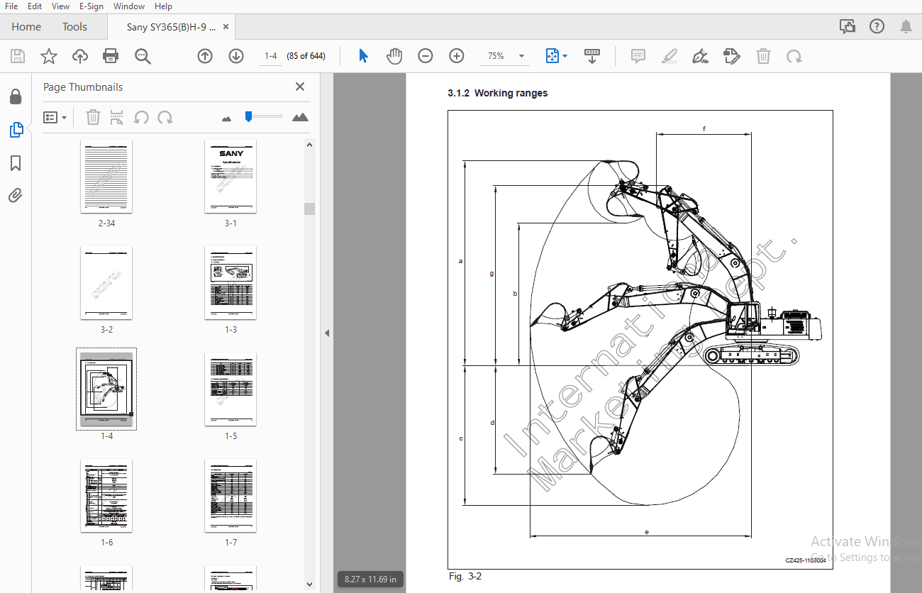
TABLE OF CONTENTS:
Sany SY365(B)H-9 Crawler Hydraulic Excavator Service Manual – PDF DOWNLOAD
1 Introduction
1 1 How to Read the Manual 1-3
1 1 1 Shop manual organization 1-3
1 1 2 Revision and distribution 1-4
1 1 3 Symbols 1-5
1 1 4 Units 1-5
1 2 Technical Terms 1-6
1 2 1 Standard size and tolerance 1-6
1 2 2 Standard clearance and value 1-7
1 2 3 Standard interference 1-7
1 2 4 Repair limit and allowable value 1-8
1 2 5 Clearance limit 1-8
1 2 6 Interference limit 1-8
1 3 Handling Electrical and Hydraulic Components 1-9
1 3 1 Points to remember when handling electric components 1-9
1 3 1 1 Handling wiring harnesses and connectors 1-9
1 3 1 2 Main failures occurring in wiring harness 1-10
1 3 1 3 Removing, installing, and drying connectors and wiring harnesses 1-12
1 3 1 4 Handling the integrated control monitor 1-16
1 3 1 5 Electric circuits troubleshooting precautions 1-17
1 3 2 Points to remember when handling hydraulic equipment 1-18
1 3 2 1 Be careful of the operating environment 1-18
1 3 2 2 Disassembly and maintenance work in the fi eld 1-18
1 3 2 3 Sealing openings 1-18
1 3 2 4 Do not let any dirt or dust get in during refi lling operations 1-19
1 3 2 5 Change hydraulic oil when the temperature is high 1-19
1 3 2 6 Flushing operations 1-19
1 3 2 7 Cleaning operations 1-20
1 4 Hose Connector 1-20
1 4 1 Type of hose connector 1-21
1 4 2 Hose connector tightening torque table 1-21
1 4 3 Connection of O-rings 1-22
1 5 Table of Standard Tightening Torques 1-23
1 6 Type of Bolts 1-24
1 7 Tightening Sequence 1-24
1 8 Maintenance of Half Flanges 1-25
1 8 1 Table of tightening torques for half fl ange bolts 1-25
1 8 2 Temperature 1-31
2 Shop Safety
2 1 Hazard Alert Information 2-3
2 2 General Shop Safety 2-5
2 2 1 Rules and shop behavior 2-6
2 2 2 Housekeeping 2-6
2 2 3 Shop Liquids Storage 2-7
2 2 4 Cleaning the Parts 2-7
2 2 5 Cleaning the Machine 2-8
2 2 6 Appropriate Working Apparel 2-8
2 2 7 Personal Protective Equipment 2-8
2 2 8 Using the Correct Tools 2-9
2 2 9 Fire Extinguisher and Emergency Exits 2-9
2 2 10 Electrical Dangers 2-10
2 2 11 Hoisting a Load 2-10
2 3 Before Repair 2-11
2 3 1 Safe Work Preparations 2-11
2 3 2 Preparing yourself 2-12
2 3 3 Lockout/Tagout 2-13
2 3 4 Two people when engine running 2-15
2 3 5 Safety Partners 2-15
2 4 Repair Precautions 2-16
2 4 1 Running the Machine 2-16
2 4 2 Mounting and Dismounting 2-17
2 4 3 Removing Attachments 2-18
2 4 4 Jacking Up the Machine 2-18
2 4 5 Adding Fluids to a System 2-18
2 4 6 Aligning Parts or Components 2-19
2 4 7 Driving Pins 2-19
2 4 8 When compressed air is used 2-19
2 4 9 Welding operation 2-20
2 4 10 Track Recoil Springs 2-20
2 4 11 High-Pressure Fluid Lines 2-21
2 4 12 Air-conditioning system maintenance 2-22
2 4 13 High voltage precautions 2-22
2 4 14 Disconnecting the System Power 2-23
2 4 15 Accumulator 2-23
2 4 17 Battery Hazards 2-24
2 4 18 Jump-Start Safety 2-25
2 4 19 Avoiding fi re and explosion 2-26
2 4 20 Chemical hazard 2-27
2 4 21 Material Safety Data Sheets (MSDS) 2-27
2 4 22 Proper disposal of wastes 2-28
2 5 Other Precautions 2-29
2 5 1 Sling work and giving signals 2-29
2 5 2 Using mobile crane 2-31
2 5 3 Using overhead hoist crane 2-31
2 5 4 Selecting wire ropes 2-33
3 Specifi cations
3 1 Specifi c Dimension 1-3
3 1 1 Dimension 1-3
3 1 2 Working ranges 1-4
3 2 Technical Specifi cations 1-5
3 3 Weight Table 1-7
3 4 Engine oil, Fuel and Coolant 1-8
3 5 Engine Performance Curves 1-9
4 Structure and Functions
4 1 Engine and Cooling System 4-5
4 1 1 Engine-related parts 4-5
4 1 2 Radiator and intercooler 4-6
4 2 Power Train 4-7
4 2 1 Overview 4-7
4 2 2 Travel reducer AS 4-8
4 2 3 Swing reducer mechanism 4-10
4 2 4 Swing bearing 4-12
4 3 Undercarriage Travel System 4-14
4 3 1 Track frame and tensioning mechanism 4-14
4 3 2 Idler 4-16
4 3 3 Carrier roller 4-18
4 3 4 Track roller 4-19
4 3 5 Track 4-20
4 3 6 Tri-grouser track shoe 4-23
4 4 Hydraulic System, Part 1 4-24
4 4 1 Deployment of hydraulic parts 4-24
4 4 2 Hydraulic tank and fi lter 4-26
4 4 3 Hydraulic pump 4-28
4 4 3 1 Outline 4-29
4 4 3 2 Function 4-31
4 4 3 3 Structure 4-31
4 4 3 4 Operating principle 4-32
4 4 3 5 Oil delivery control 4-33
4 4 4 Pilot pump 4-34
4 4 5 Regulator 4-35
4 5 Hydraulic system, Part 2 4-48
4 5 1 Main control valve 4-48
4 5 1 1 Overview 4-48
4 5 1 2 Main valve structure 4-50
4 5 2 Hydraulic circuit (With bucket confl uence function) 4-56
4 6 Hydraulic System, Part 3 4-79
4 6 1 Swing motor 4-79
4 6 2 Swing holding brake 4-81
4 6 3 Relief valve section 4-82
4 6 4 Anti-jerk valve 4-84
4 6 4 1 Operation diagram 4-84
4 6 4 2 Effect illustration 4-84
4 6 5 Central Swivel Joint 4-86
4 6 6 Travel motor 4-87
4 6 7 Reducer 4-89
4 6 8 Travel motor (Nabtesco) 4-91
4 6 9 Operating principle of the basic components 4-93
4 6 9 1 Double-balanced valve 4-93
4 6 9 2 Operation of parking brake 4-98
4 6 9 3 Operation of braking valve 4-99
4 6 10 Control system 4-108
4 6 11 Manual pilot valve 4-110
4 6 12 Travel pilot valve 4-114
4 6 12 1 Operating principle 4-116
4 6 13 Solenoid valve 4-118
4 6 14 PPC accumulator 4-119
4 6 15 Pilot oil fi lter 4-121
4 6 16 Hydraulic cylinders 4-122
4 6 16 2 Lubrication at every 100 service hours 4-123
4 6 16 1 Lubrication at every 500 service hours 4-123
4 7 Work Equipment 4-124
4 7 1 Component dimensions 4-124
4 7 2 Arm dimensions 4-126
4 7 2 1 Bucket dimensions 4-128
4 8 Operator Station and Its Attachments 4-130
4 8 1 Air conditioner lines 4-130
4 8 1 1 Layout of A/C components 4-132
4 8 1 2 A/C control panel 4-133
4 8 1 3 Diagram of electrical circuit 4-134
4 8 1 4 Operating principle 4-136
4 8 1 5 Compressor 4-137
4 8 1 6 Clutch 4-139
4 8 1 7 Condenser 4-140
4 8 1 8 Expansion valve 4-141
4 8 1 9 Evaporator 4-141
4 8 1 10 Dehydrator 4-142
4 8 1 11 Pressure switch 4-143
4 8 1 12 Fresh air sensor 4-144
4 8 2 Refrigerant 4-145
4 8 2 1 Compressor oil 4-163
4 9 Engine Control 4-164
4 9 1 System operation 4-165
4 9 1 1 Engine starting 4-165
4 9 1 2 Engine speed control 4-165
4 9 1 3 Engine shutdown 4-165
4 9 2 System components 4-166
4 9 2 1 Fuel control dial 4-166
4 9 2 2 Controller 4-168
4 10 Electrical Control System 4-170
4 10 1 Control function 4-170
4 10 2 Diagram of machine control system 4-171
4 10 3 Engine-pump combination control 4-173
4 10 4 Pump control function 4-177
4 10 4 1 Constant power control 4-180
4 10 4 2 ESS control 4-180
4 10 5 Valve control function 4-181
4 10 6 Dual travel speed control 4-183
4 10 7 Engine preheat/overheat alarm 4-185
4 10 8 Auto deceleration/acceleration control 4-187
4 10 9 Engine speed calibration function 4-188
4 10 10 System parts and components 4-190
4 11 Monitoring System 4-195
4 11 1 Monitor 4-196
4 11 2 Monitor panel 4-197
4 11 2 1 Alert and signal indicators 4-197
4 11 2 2 Operation keys 4-199
4 11 3 Monitor display and operation 4-201
4 11 3 1 Default page 4-201
4 11 3 2 Password entry to system information 4-202
4 11 3 3 Main menu 4-202
4 11 3 4 Engine & throttle signals 4-203
4 11 3 5 Pilot pressure signals 4-203
4 11 3 6 Main pump & main valve signals 4-204
4 11 3 7 Failure codes 4-204
4 11 3 8 Throttle help information 4-205
4 11 3 9 Language selection 4-205
4 11 3 10 System clock setup 4-206
4 11 3 11 GPS information 4-207
4 11 3 12 System setup 4-208
4 11 3 13 Machine confi guration 4-208
4 11 3 14 Service hour setup 4-209
4 11 3 15 Machine confi guration setup 4-210
4 11 3 16 Hydraulic oil temperature 4-211
4 11 3 17 Screen brightness setup 4-211
4 11 3 18 System lockout (level 1) 4-212
4 11 3 19 System lockout (level 2) 4-212
5 Table of Standard Values
5 1 Standard Values for Engine-Related Parts 5-3
5 2 Standard Values for Chassis-Related Parts 5-4
6 Testing and adjusting
6 1 Engine Speed – Test and Adjust 6-3
6 2 Exhaust Gas Color – Test 6-5
6 3 Valve Clearance – Adjust 6-7
6 3 1 Testing 6-8
6 3 2 Adjusting 6-9
6 4 Compression force – Test 6-10
6 5 Fuel Injection Timing – Test and Adjust 6-13
6 5 1 Testing 6-14
6 5 2 Adjusting 6-18
6 6 A/C Compressor Belt Tension – Test and Adjust 6-19
6 6 1 Testing 6-19
6 6 2 Adjusting 6-19
6 7 Swing Bearing Clearance – Test 6-20
6 8 Track Tensioner – Test and Adjust 6-21
6 8 1 Testing 6-21
6 8 2 Adjusting 6-22
6 9 Oil in Hydraulic Circuits – Test and Adjust 6-23
6 9 1 Testing 6-23
6 9 2 Adjusting 6-25
6 10 Control Oil Circuit Pressure – Test and Adjust 6-28
6 10 1 Testing 6-28
6 10 2 Adjusting 6-28
6 11 Solenoid Valve Output Pressure – Test 6-29
6 12 Pilot Valve Output Pressure – Test 6-31
6 13 Work Equipment and Swing Pilot Valves – Adjust 6-33
6 14 Hydraulic Drift of Work Equipment – Test 6-34
6 15 Remaining Pressure in Hydraulic Lines – Relieve 6-36
6 16 Oil Leakage Amount – Test 6-37
6 17 Air in Each Component – Purge 6-41
7 Troubleshooting
7 1 Checks before Troubleshooting 7-5
7 2 Failure Symptoms and Troubleshooting Codes 7-6
7 3 Connector Location and Electrical Circuit Diagram 7-9
7 3 1 Connector location layout 7-13
7 3 2 Diagram of system electrical elements 7-18
7 3 3 Diagram of electrical control system 7-20
7 3 4 SWP connectors 7-22
7 3 5 A/AMP connectors 7-23
7 3 6 DT connectors 7-24
7 4 Troubleshooting with an Event Code 7-25
7 5 Troubleshooting Electrical System (E-Mode) 7-49
7 6 Troubleshooting Hydraulic and Mechanical Systems (H-mode) 7-81
8 Disassembly and Assembly
8 1 How to Read This Manual 8-5
8 1 1 Removing and installing an assembly 8-5
8 2 Operating Precautions 8-6
8 3 Start Motor AS 8-9
8 3 1 Removal 8-9
8 3 2 Installation 8-9
8 4 Fuel Injection Pump AS 8-10
8 4 1 Removal 8-10
8 4 2 Installation 8-12
8 5 Engine Front Oil Seal 8-13
8 5 1 Removal 8-13
8 5 2 Installation 8-13
8 6 Engine Rear Oil Seal 8-14
8 6 1 Removal 8-14
8 6 2 Installation 8-14
8 7 Cylinder Head AS 8-15
8 7 1 Removal 8-15
8 7 2 Installation 8-19
8 8 Radiator AS 8-20
8 8 1 Removal 8-20
8 8 2 Installation 8-23
8 9 Engine and Hydraulic Pump AS 8-24
8 9 1 Removal 8-24
8 9 2 Installation 8-30
8 10 Final Drive AS 8-31
8 10 1 Removal 8-31
8 10 2 Installation 8-32
8 11 Final Drive AS 8-33
8 11 1 Disassembly 8-33
8 11 2 Assembly 8-36
8 12 Swing Motor and Swing Drive AS 8-42
8 12 1 Removal 8-42
8 12 2 Installation 8-43
8 13 Swing Motor and Swing Drive AS 8-44
8 13 1 Disassembly 8-44
8 13 2 Assembly 8-49
8 14 Idler AS 8-54
8 14 1 Disassembly 8-54
8 14 2 Assembly 8-55
8 15 Sprocket 8-58
8 15 1 Removal 8-58
8 15 2 Installation 8-58
8 16 Track AS 8-59
8 16 1 Removal 8-59
8 16 2 Installation 8-60
8 17 Swing Bearing AS 8-62
8 17 1 Removal 8-62
8 17 2 Installation 8-63
8 18 Swing frame AS 8-64
8 18 1 Removal 8-64
8 18 2 Installation 8-66
8 19 Swivel Joint AS 8-67
8 19 1 Removal 8-67
8 19 2 Installation 8-69
8 20 Central Swivel Joint AS 8-70
8 20 1 Disassembly 8-70
8 20 2 Assembly 8-70
8 21 Hydraulic Tank AS 8-71
8 21 1 Removal 8-71
8 21 2 Installation 8-73
8 22 Control Valve AS 8-74
8 22 1 Removal 8-74
8 22 2 Installation 8-79
8 23 Hydraulic Pump AS 8-80
8 23 1 Removal 8-80
8 23 2 Installation 8-83
8 24 Middle Oil Seal (Hydraulic Pump Input Shaft) 8-84
8 24 1 Removal 8-84
8 24 2 Installation 8-84
8 25 Pilot Valve AS (Work Equipment) 8-85
8 26 Travel Pilot Valve AS 8-86
8 27 Hydraulic Cylinder AS 8-87
8 27 1 Disassembly 8-88
8 27 2 Assembly 8-92
8 28 Work Equipment AS 8-97
8 28 1 Removal 8-97
8 28 2 Installation 8-99
8 29 Air Conditioner AS 8-100
8 29 1 Removal 8-100
8 29 2 Installation 8-103
8 30 Counterweight AS 8-104
8 30 1 Removal 8-104
8 30 2 Installation 8-105
8 31 Cab AS 8-106
8 31 1 Removal 8-106
8 31 2 Installation 8-109
8 32 Cab Window Glass 8-110
8 32 1 Removal 8-111
8 32 2 Installation 8-114
8 33 Front Window AS 8-126
8 33 1 Disassembly 8-126
8 33 2 Assembly 8-129
8 34 Monitor – Remove and Install 8-135
8 34 1 Removal 8-135
8 34 2 Installation 8-135
8 35 Controller AS 8-136
8 35 1 Removal 8-136
8 35 2 Installation 8-136
8 36 Radio 8-137
8 36 1 Structure 8-137
8 36 2 Removal and installation 8-139
8 36 3 Connector model and wiring 8-140
8 37 Battery 8-141
8 37 1 Structure 8-141
8 37 2 Removal and installation 8-142
8 37 3 Replacement 8-143
8 38 Start Switch 8-144
8 38 1 Structure 8-144
8 38 2 Removal 8-145
8 38 3 Working principle 8-146
8 38 4 Wiring 8-146
8 39 Fuse Box 8-147
8 40 Wiper 8-148
8 40 1 Structure 8-148
8 40 2 Working principle 8-149
8 40 3 Removal 8-150
8 40 4 Installation 8-150
8 40 5 Angle adjustment of wiper arm 8-151
8 41 Relays 8-152
8 41 1 Engine relays 8-152
8 41 2 Other relays 8-153
8 41 3 Removal and installation 8-154
8 41 4 Relay connector and wiring 8-154
8 42 Sensors 8-155
8 43 Connector Terminals 8-157
8 43 1 Insertion 8-157
8 43 2 Removal 8-158
9 System Schematics
9 1 Diagram of Hydraulic Lines 9-3
9 2 Electrical diagram of chassis 9-4
9 3 Electrical diagram of control switches 9-5
9 4 Electrical diagram of operator station 9-6
9 5 Electrical diagram of air conditioner 9-7
9 6 Electrical diagram of monitor 9-8
More products