$39
Sany SY50U Crawler Hydraulic Excavator Service Manual – PDF DOWNLOAD
Sany SY50U Crawler Hydraulic Excavator Service Manual – PDF DOWNLOAD
FILE DETAILS:
Sany SY50U Crawler Hydraulic Excavator Service Manual – PDF DOWNLOAD
Language : English
Pages : 452
Downloadable : Yes
File Type : PDF
IMAGES PREVIEW OF THE MANUAL:
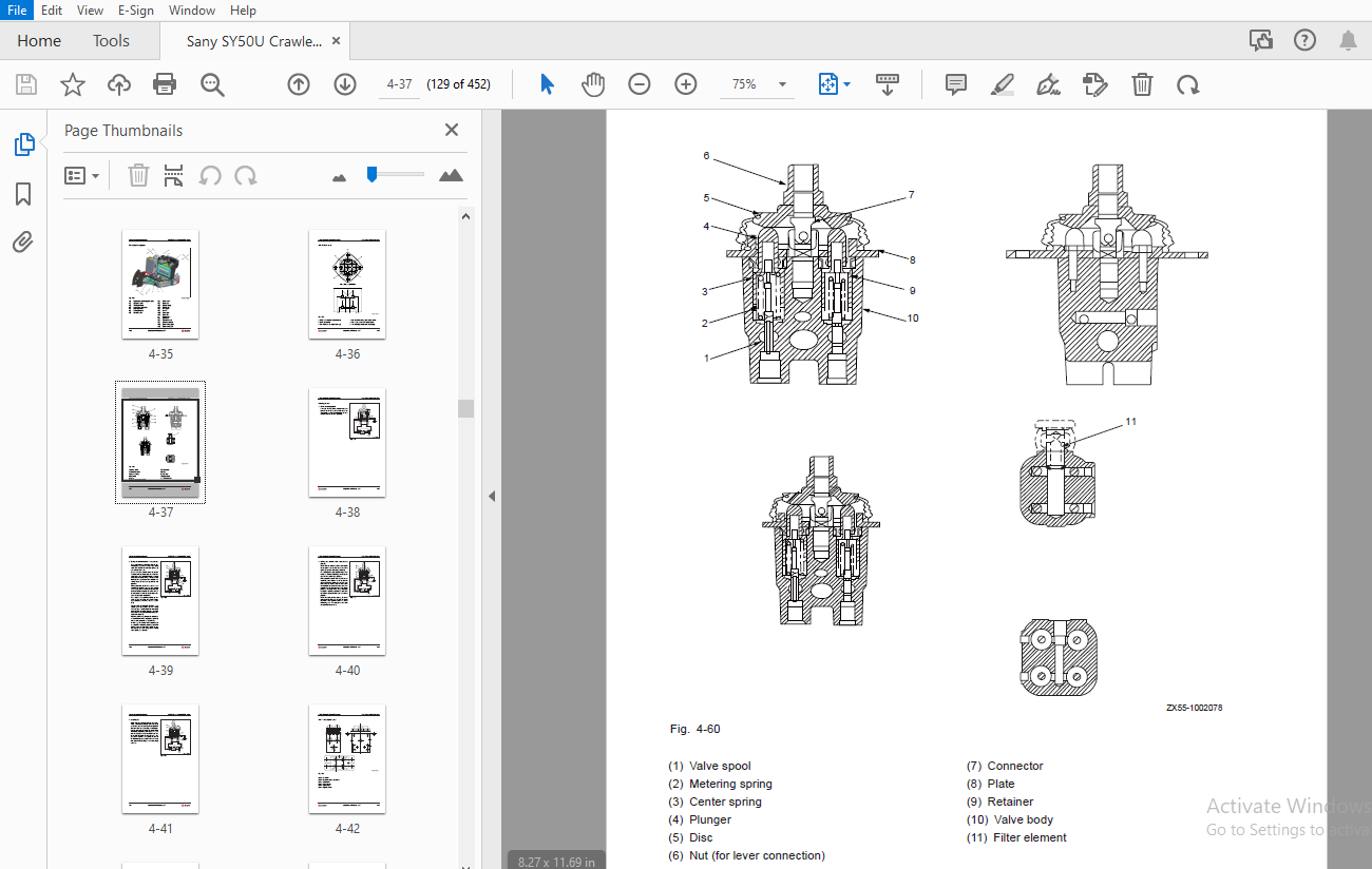
TABLE OF CONTENTS:
Sany SY50U Crawler Hydraulic Excavator Service Manual – PDF DOWNLOAD
1 Introduction
1 1 How to Read the Manual 1-3
1 1 1 Shop manual organization 1-3
1 1 2 Revision and distribution 1-4
1 1 3 Symbols 1-5
1 1 4 Units 1-5
1 2 Technical Terms 1-6
1 2 1 Standard size and tolerance 1-6
1 2 2 Standard clearance and value 1-7
1 2 3 Standard interference 1-7
1 2 4 Repair limit and allowable value 1-8
1 2 5 Clearance limit 1-8
1 2 6 Interference limit 1-8
1 3 Handling Electrical and Hydraulic Components 1-9
1 3 1 Points to remember when handling electric components 1-9
1 3 1 1 Handling wiring harnesses and connectors 1-9
1 3 1 2 Main failures occurring in wiring harness 1-10
1 3 1 3 Removing, installing, and drying connectors and wiring harnesses 1-12
1 3 1 4 Handling the integrated control monitor 1-16
1 3 1 5 Electric circuits troubleshooting precautions 1-17
1 3 2 Points to remember when handling hydraulic equipment 1-18
1 3 2 1 Be careful of the operating environment 1-18
1 3 2 2 Disassembly and maintenance work in the f eld 1-18
1 3 2 3 Sealing openings 1-18
1 3 2 4 Do not let any dirt or dust get in during ref lling operations 1-19
1 3 2 5 Change hydraulic oil when the temperature is high 1-19
1 3 2 6 Flushing operations 1-19
1 3 2 7 Cleaning operations 1-20
1 4 Hose Connector 1-20
1 4 1 Type of hose connector 1-21
1 4 2 Hose connector tightening torque table 1-21
1 4 3 Connection of O-rings 1-22
1 5 Table of Standard Tightening Torques 1-23
1 6 Type of Bolts 1-24
1 7 Tightening Sequence 1-24
1 8 Maintenance of Half Flanges 1-25
1 8 1 Table of tightening torques for half f ange bolts 1-25
1 8 2 Temperature 1-31
2 Shop Safety
2 1 Hazard Alert Information 2-3
2 2 General Shop Safety 2-5
2 2 1 Rules and shop behavior 2-6
2 2 2 Housekeeping 2-6
2 2 3 Shop Liquids Storage 2-7
2 2 4 Cleaning the Parts 2-7
2 2 5 Cleaning the Machine 2-8
2 2 6 Appropriate Working Apparel 2-8
2 2 7 Personal Protective Equipment 2-8
2 2 8 Using the Correct Tools 2-9
2 2 9 Fire Extinguisher and Emergency Exits 2-9
2 2 10 Electrical Dangers 2-10
2 2 11 Hoisting a Load 2-10
2 3 Before Repair 2-11
2 3 1 Safe Work Preparations 2-11
2 3 2 Preparing yourself 2-12
2 3 3 Lockout/Tagout 2-13
2 3 4 Two people when engine running 2-15
2 3 5 Safety Partners 2-15
2 4 Repair Precautions 2-16
2 4 1 Running the Machine 2-16
2 4 2 Mounting and Dismounting 2-17
2 4 3 Removing Attachments 2-18
2 4 4 Jacking Up the Machine 2-18
2 4 5 Adding Fluids to a System 2-18
2 4 6 Aligning Parts or Components 2-19
2 4 7 Driving Pins 2-19
2 4 8 When compressed air is used 2-19
2 4 9 Welding operation 2-20
2 4 10 Track Recoil Springs 2-20
2 4 11 High-Pressure Fluid Lines 2-21
2 4 12 Air-conditioning system maintenance 2-22
2 4 13 High voltage precautions 2-22
2 4 14 Disconnecting the System Power 2-23
2 4 15 Accumulator 2-23
2 4 17 Battery Hazards 2-24
2 4 18 Jump-Start Safety 2-25
2 4 19 Avoiding f re and explosion 2-26
2 4 20 Chemical hazard 2-27
2 4 21 Material Safety Data Sheets (MSDS) 2-27
2 4 22 Proper disposal of wastes 2-28
2 5 Other Precautions 2-29
2 5 1 Sling work and giving signals 2-29
2 5 2 Using mobile crane 2-31
2 5 3 Using overhead hoist crane 2-31
2 5 4 Selecting wire ropes 2-33
3 Specif cations
3 1 Dimension Drawing 3-3
3 2 Working Ranges 3-4
3 3 Technical Specif cations 3-5
3 4 Weight Table 3-7
3 5 Capacity Table 3-8
3 6 Fuel and Coolant Capacities 3-9
3 7 Engine Performance Curve 3-10
4 Structure and Functions
4 1 Engine and Cooling System 4-3
4 1 1 Water cooler and oil cooler 4-3
4 1 2 Engine control device 4-5
4 2 Power Train 4-7
4 2 1 Power transmission system 4-7
4 2 2 Swing bearing 4-8
4 2 3 Swing motor 4-9
4 3 Undercarriage 4-10
4 3 1 Track frame 4-10
4 3 2 Tensioning device 4-11
4 3 3 Tensioning device 4-12
4 4 Hydraulic System 4-13
4 4 1 Hydraulic lines 4-13
4 4 2 Hydraulic tank 4-14
4 4 3 Hydraulic pump 4-15
4 4 4 Control valve 4-17
4 4 5 Swing motor 4-22
4 4 6 Safety valve 4-26
4 4 7 Central swivel joint 4-28
4 4 8 Travel motor 4-29
4 4 8 1 Working process of parking brake 4-32
4 4 8 2 Working process of brake valve 4-33
4 4 9 Control system 4-35
4 4 10 Pilot valve 4-36
4 4 11 Travel pilot valve 4-42
4 4 12 Oil source control valve 4-46
4 4 13 Backup pilot valve 4-47
4 4 14 Hydraulic cylinders 4-51
4 5 Air Conditioner System 4-52
4 5 1 Electric circuit 4-52
4 5 2 Component locations 4-53
4 5 3 Checking condenser f ns 4-55
4 5 4 Refrigerant-f lling operation 4-56
4 5 5 Troubleshooting with a manifold pressure gauge 4-57
4 6 Electrical System 4-66
4 6 1 Electrical circuit diagram 4-67
4 7 Electronic Control System 4-68
4 7 1 General view 4-68
4 7 2 Functional overview of electrical control system 4-69
4 7 3 Valve control function 4-71
4 7 4 preheating and overheating protection function 4-73
4 7 5 Travel speed selection 4-74
4 7 6 Machine monitoring system 4-75
4 8 Integrated-controlled Monitor System 4-77
4 8 1 Monitor 4-77
4 8 2 Page introduction and operation 4-80
4 8 2 1 Main menu 4-80
4 8 2 2 Alert information 4-81
4 8 2 3 History fault information 4-82
4 8 2 4 System information 4-82
4 8 2 5 Maintenance information 4-83
4 8 2 6 GPS monitoring and rpm calibration 4-83
4 8 2 7 Machine conf guration setup 4-84
4 8 2 8 System lockout 4-85
4 8 2 9 Password entry 4-86
4 8 2 10 System lockout 4-87
4 8 2 11 One-key call 4-88
5 Standard Values
5 1 Standard Values for Engine-Related Parts 5-3
5 2 Standard Values for Chassis-Related Parts 5-4
5 3 Standard Values for Electrical Parts 5-11
6 Testing and Adjusting
6 1 Engine Speed – Test 6-4
6 2 Exhaust Gas Color – Test 6-5
6 2 1 Using a hand tester 6-5
6 2 2 Using an instrument 6-6
6 3 Valve Clearance – Adjust 6-7
6 4 Compression Pressure – Test 6-8
6 5 Injection Timing – Test and Adjust 6-9
6 5 1 Checking injection timing 6-9
6 5 2 Adjusting the injection timing 6-12
6 6 Engine Oil Pressure – Test 6-13
6 7 Alternator Belt Tension – Test and Adjust 6-13
6 8 Hydraulic Pressure in Oil Circuits – Test and Adjust 6-14
6 9 LS Differential Pressure and LS Valve – Test/Adjust 6-16
6 9 1 Testing LS differential pressure 6-16
6 9 2 Adjusting LS valve 6-17
6 10 Hydraulic Pressure in Control Circuit – Test 6-18
6 11 Pilot Valve Output Pressure – Test 6-19
6 12 Work Equipment and Swing Pilot Valve – Adjust 6-20
6 13 Travel Deviation – Test 6-21
6 14 Oil Leakage – Test 6-22
6 14 1 Work equipment cylinder 6-22
6 14 2 Swing motor 6-24
6 14 3 Travel motor 6-25
6 15 Residual Pressure in Hydraulic Circuit – Release 6-26
6 16 Swing Bearing Clearance – Check 6-27
6 17 Track Tension – Check and Adjust 6-28
6 17 1 Checking track tension 6-28
6 17 2 Adjusting track tension 6-28
6 17 2 1 When the tension is high 6-28
6 17 2 2 When the tension is low 6-29
6 18 Air Purging 6-30
6 18 1 Purging air from hydraulic pump 6-30
6 18 2 Purging air from hydraulic cylinder 6-31
6 18 3 Purging air from swing motor 6-31
6 18 4 Purging air from travel motor 6-31
7 Troubleshooting
7 1 Troubleshooting Precautions 7-3
7 2 Checks Before Troubleshooting 7-5
7 3 Connector Locations and System Diagrams 7-6
7 4 Number of Pins Required for Connection 7-9
7 5 Electric Wire Specif cations 7-16
7 6 How to Use the Judgement Chart 7-18
7 7 How to Use a Schematic Diagram for Troubleshooting 7-20
7 8 Troubleshooting the Electrical System 7-21
7 9 Troubleshooting the Engine 7-28
7 10 Troubleshooting the Hydraulic and Mechanical System 7-53
8 Disassembly and Assembly
8 1 Operating Precautions 8-6
8 2 Engine and Main Pump AS 8-9
8 2 1 Removal 8-10
8 2 2 Installation 8-14
8 3 Central Swivel Joint AS 8-15
8 3 1 Removal 8-15
8 3 2 Installation 8-16
8 3 3 Disassembly 8-17
8 3 4 Assembly 8-17
8 4 Sprocket 8-18
8 4 1 Removal 8-18
8 4 2 Installation 8-18
8 5 Travel Motor AS 8-19
8 5 1 Removal 8-19
8 5 2 Installation 8-20
8 5 3 Disassembly 8-21
8 5 3 1 Preparatory work 8-21
8 5 3 2 General precautions for disassembling 8-21
8 5 3 3 Disassembling procedure 8-22
8 5 4 Table of maintenance standard 8-32
8 5 5 Assembly 8-35
8 5 5 1 Preparatory work 8-35
8 5 5 2 General precautions 8-35
8 5 5 3 Assembly procedure 8-36
8 5 5 4 Performance test 8-50
8 6 Swing Motor and Swing Mechanism AS 8-51
8 6 1 Removal 8-51
8 6 2 Installation 8-52
8 7 Swing Motor AS 8-53
8 7 1 Disassembly 8-53
8 7 1 1 Separate the motor from the reducer 8-53
8 7 1 2 Disassemble the motor 8-53
8 7 1 3 Disassembling the reducer 8-59
8 7 1 4 Assembling the motor 8-62
8 7 1 5 Assemble the reducer 8-70
8 7 1 6 Assembling the swing motor assembly 8-74
8 8 Swing Mechanism AS 8-75
8 8 1 Disassembly 8-75
8 8 2 Assembly 8-78
8 9 Swing Platform AS 8-82
8 9 1 Removal 8-82
8 9 2 Installation 8-84
8 10 Swing Bearing AS 8-85
8 10 1 Removal 8-85
8 10 2 Installation 8-85
8 11 Idler and Tension Spring AS 8-86
8 11 1 Removal 8-86
8 11 2 Installation 8-86
8 12 Tension Spring AS 8-87
8 12 1 Disassembly 8-87
8 12 2 Assembly 8-88
8 13 Idler AS 8-89
8 13 1 Disassembly 8-89
8 13 2 Assembly 8-89
8 14 Track Roller AS 8-90
8 14 1 Removal 8-90
8 14 2 Installation 8-90
8 15 Track Roller AS 8-91
8 15 1 Disassembly 8-91
8 15 2 Assembly 8-91
8 16 Carrier Roller AS 8-92
8 16 1 Removal 8-92
8 16 2 Installation 8-92
8 17 Track AS 8-93
8 17 1 Removal 8-93
8 17 2 Installation 8-93
8 18 Hydraulic Tank AS 8-94
8 18 1 Removal 8-94
8 18 2 Installation 8-94
8 19 Main Pump AS 8-95
8 19 1 Removal 8-95
8 18 2 Installation 8-95
8 20 Control Valve AS 8-96
8 21 1 Removal 8-96
8 21 2 Installation 8-96
8 21 Oil Source Control Valve AS 8-97
8 22 1 Removal 8-97
8 22 2 Installation 8-97
8 22 Left Pilot Valve AS (Arm and Swing Control) 8-98
8 22 1 Removal 8-98
8 22 2 Installation 8-98
8 23 Right Pilot Valve (Boom and Bucket Control) 8-99
8 23 1 Removal 8-99
8 23 2 Installation 8-99
8 24 Work Equipment Pilot Valve AS 8-100
8 24 1 Disassembly 8-100
8 24 2 Assembly 8-101
8 25 Travel Pilot Valve AS 8-102
8 25 1 Removal 8-102
8 25 2 Installation 8-102
8 26 Travel Pilot Valve AS 8-103
8 26 1 Disassembly 8-103
8 26 2 Assembly 8-103
8 27 Boom Cylinder AS 8-104
8 27 1 Removal 8-104
8 27 2 Installation 8-105
8 28 Arm Cylinder AS 8-106
8 28 1 Removal 8-106
8 28 2 Installation 8-107
8 29 Bucket Cylinder AS 8-108
8 29 1 Removal 8-108
8 29 2 Installation 8-109
8 30 Def ection Cylinder AS 8-110
8 30 1 Removal 8-110
8 30 2 Installation 8-110
8 31 Dozer Blade Cylinder AS 8-111
8 31 1 Removal 8-111
8 31 2 Installation 8-112
8 32 Hydraulic Cylinder AS 8-113
8 32 1 Disassembly 8-113
8 32 2 Assembly 8-116
8 33 Work Equipment AS 8-119
8 33 1 Removal 8-119
8 33 2 Installation 8-120
8 34 Bucket-Arm AS 8-121
8 34 1 Removal 8-121
8 34 2 Installation 8-122
8 35 Bucket AS 8-123
8 35 1 Removal 8-123
8 35 2 Installation 8-124
8 36 Arm AS 8-125
8 36 1 Removal 8-125
8 36 2 Installation 8-126
8 37 Boom AS 8-127
8 37 1 Removal 8-127
8 37 2 Installation 8-128
8 38 1 Removal 8-129
8 38 2 Installation 8-129
8 38 3 Installation 8-130
8 39 Dozer Blade AS 8-131
8 39 1 Removal 8-131
8 39 2 Installation 8-131
8 40 Cab AS 8-132
8 40 1 Removal 8-132
8 41 2 Installation 8-133
8 42 Monitor AS 8-134
8 42 1 Removal 8-134
8 42 2 Installation 8-134
9 Maintenance Standard
9 1 Swing Mechanism 9-3
9 2 Swing Bearing 9-4
9 3 Track Frame 9-5
9 4 Idler 9-6
9 5 Track Roller 9-7
9 6 Rubber track 9-8
9 7 Work Equipment 9-9
9 8 Arm Dimensions 9-11
9 9 Bucket Dimensions 9-12
9 10 Hydraulic Cylinder 9-13
10 System Schematics
10 1 Hydraulic Circuit Diagram 10-3
10 2 General System Diagram (1/5) 10-4
10 3 General System Diagram (2/5) 10-5
10 4 General System Diagram (3/5) 10-6
10 5 General System Diagram (4/5) 10-7
10 6 General System Diagram (5/5) 10-8
10 7 Electrical Circuit Diagram 10-9
More products