$34
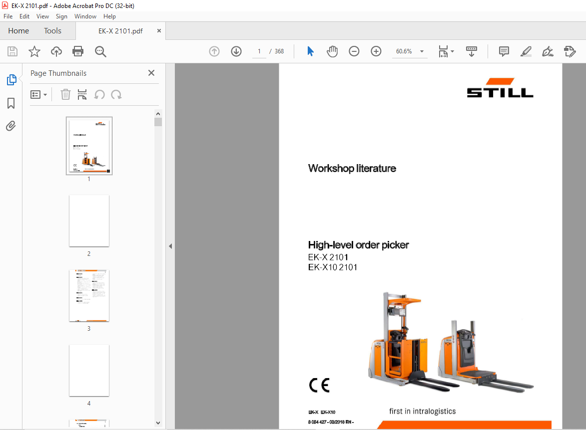
Still EK-X 2101 EK-X10 2101 Forklift Workshop Manual 8054427 – PDF DOWNLOAD
Still EK-X 2101 EK-X10 2101 Forklift Workshop Manual 8054427 – PDF DOWNLOAD
FILE DETAILS:
Still EK-X 2101 EK-X10 2101 Forklift Workshop Manual 8054427 – PDF DOWNLOAD
Language : English
Pages : 368
Downloadable : Yes
File Type : PDF
TABLE OF CONTENTS:
Still EK-X 2101 EK-X10 2101 Forklift Workshop Manual 8054427 – PDF DOWNLOAD
00 Product information
Safety 00-1
Safety instructions 00-1
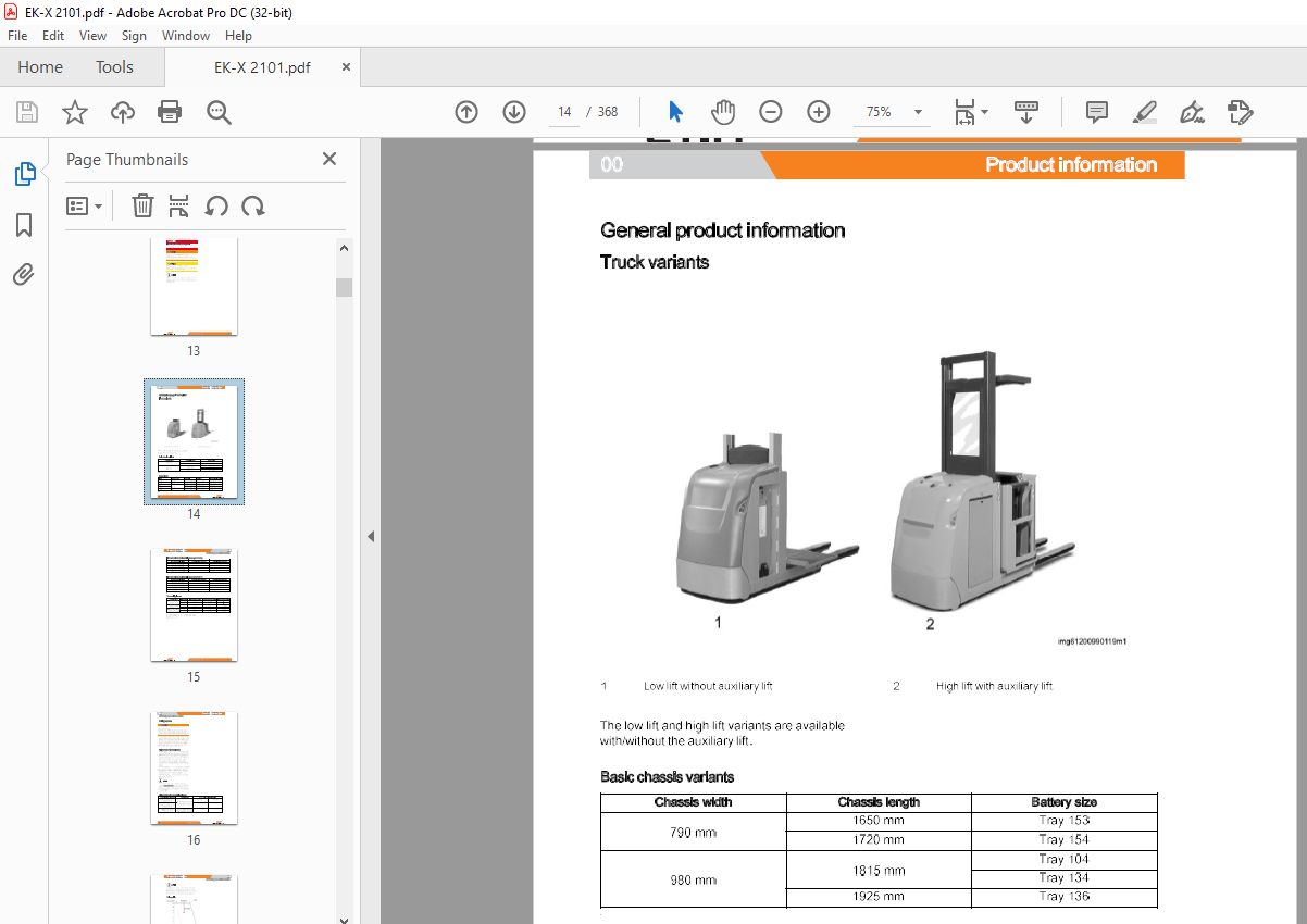
General product information 00-2
Truck variants 00-2
Driving speeds 00-4
02 Diagnostics
Software 02-1
Para Dig 02-1
General 02-1
Win Flash – General 02-7
Description 02-7
Preparation for downloading to CAN control system 02-9
Win Flash – Working with WinFlash software 02-10
General 02-10
Selecting a file 02-11
Selecting a truck 02-12
Selecting a control system 02-13
Checking the connection to the CAN control system 02-14
Start programming to CAN control systems 02-15
Close the program 02-16
Fault lists 02-11
General 02-17
Error listfor the traction controller and pump controller (FPS) A 10 02-20
Error listforoperating panel controller (BPS) 8U62, drive side (DWS) 02-41
Error listforoperating panel controller (BPS) 8U62, load side (LS) 02-43
Display error list 02-46
Error List Input/Output Extension Module (IOX) 02-48
Steering controller error list 02-54
Error listfor steering unit (ES30-24) 3M 1 02-60
Inductive guidance (IZF) error list 02-77
Error listforoperating panel controller (BPS) 8U62, drive side (DWS) 02-114
Error listforoperating panel controller (BPS) 8U62, load side (LS) 02-116
Error list IOZ1 02-119
Error list IOZ2 02-122
Teach-In 02-124
Distance sensor main lift 02-124
–·· 8 054 427 -03/2018 EN- Ill
Table of contents
11 Electric motor
Traction motor 11-1
General
Testing
11-1
11-2
Repair 11-3
Speed sensor 11-6
General
Testing
11-6
11-7
Repair 11-8
Temperature sensor 11-9
General
Testing
11-9
11-10
Repair 11-1 0
22 Mechanical drive axle
Front bevel gears 22-1
General 22-1
Test 22-2
Repair 22-3
Maintenance 22-7
34 Driver’s compartment
Driver’s cab 34-1
Tilting order picking barrier 34-1
General (for industrial trucks from 0 1/2017) 34-1
Testing 34-3
Repairs 34-4
42 Steering
IV
Electric steering (ELK) 42-1
General 42-1
Steering motor 42-2
General 42-2
Repair 42-3
Steering controller 3A20 42-4
General 42-4
Repair 42-7
Set-point potentiometer 42-8
General 42-8
8 054 427 -03/2018 EN- –··
Table of contents
Test 42-10
Repair 42-11
Actual-value potentiometer 42-12
General 42-12
Test 42-13
Repair 42-14
Reference switch 42-15
General 42-15
Test 42-15
Repair 42-16
Electric steering (ES30-24) 3M1 42-17
General
Testing
42-17
42-20
Repairs 42-21
Setpoint device 42-23
General 42-23
Testing 42-24
Repairs 42-25
Actual value transmitter 42-26
General 42-26
Reference switch 42-26
General 42-26
Testing 42-27
Repairs 42-27
–·· 8 054 427 – 03/2018 EN – V
Table of contents
43 Mechanical rail guidance
Guide elements 43-1
General 43-1
Testing 43-1
Repairs 43-2
Aisle detection 43-3
General 43-3
Testing 43-3
44 Inductive guidance
Inductive guidance 44-1
General 44-1
Test 44-8
Repair 44-9
Controller (IZF) 3A21 44-11
General 44-11
Test 44-12
Repair 44-12
Peripherals 44-14
Antennas 44-14
General 44-14
Testing 44-15
Repairs 44-15
Guide wire 44-16
General 44-16
Frequency generator 44-17
General 44-17
Aisle detection 44-19
General 44-19
46 Wheels and tyres
VI
Wheels 46-1
Traction wheel 46-1
General 46-1
Repair 46-2
Load wheel 46-3
General 46-3
Repair 46-3
8 054 427 – 03/2018 EN – –··
Table of contents
49 Brake system
Brake system 49-1
Required braking capabilities for group C industrial trucks 49-1
Electric service brake 49-3
General 49-3
Testing 49-4
Parking brake 49-6
General 49-6
Test 49-7
Repair 49-10
Maintenance 49-14
50 Controls
Operating panel 50-1
General 50-1
Display (DIS) 8A12 50-2
Standard Display 50-2
General 50-2
Repair 50-3
LCD 50-5
General 50-5
60 Electrics/electronics
Wiring – Standard design 60-1
Repair 60-1
Sensors 60-2
Distance sensor main lift 60-2
General 60-2
Repair 60-4
Overflead guard switch 60-5
General 60-5
Testing 60-5
Repair 60-7
Other Components 60-1 o
Control board 60-10
General 60-10
Plug support cabine 60-11
General 60-11
–·· 8 054 427 -03/2018 EN- VII
Table of contents
Plug support chassis 60-27
General 60-27
64 Electronic controllers
Drive/pump controller 64-1
General 64-1
Other electronic controllers 64-5
CAN-Bus 64-5
General 64-5
Test 64-6
Input/output controller (IOZ) 8U65 64-8
General 64-8
Operating panel controller(BPS) 8U62 upto 12/2016 64-11
General 64-11
Operating panel controller(BPS) 8U62from 01/2017 64-15
General 64-15
69 Batteries and accessories
Traction batteries and accessories 69-1
Replacing the battery 69-1
Maintenance 69-4
70 Hydraulics, general
Basic hydraulics 70-1
Oil tank 70-1
General 70-1
Repair 70-2
Maintenance 70-3
Breatherfilter 70-3
General 70-3
Maintenance 70-4
71 Working hydraulics
VIII
Pump unit 71-1
General 71-1
Repair 71-2
Pump motor 71-4
General 71-4
Temperature sensor 71-5
Testing 71-5
8 054 427 -03/2018 EN- –··
Table of contents
Carbon brushes 71-5
Repairs 71-5
76 Valves
Pressure relief valve 76-1
General 76-1
Control valves 76-2
General 76-2
Proportional valve 76-3
General 76-3
Testing 76-3
Repair 76-3
Valve coil 76-5
General 76-5
Testing 76-5
Repair 76-6
80 Load support device
Mast bracing 80-1
Repair 80-1
Lift mast bearing 80-2
Telescopic lift mast 80-2
Repair 80-2
81 Lift mast
Load chains 81-1
Test steps for load chains 81-1
Lift cylinder 81-6
Bleeding 81-6
Repair 81-7
Line break safety valve 81-8
General 81-8
Line break safety valve, type 1 81-9
Single mast 81-10
General 81-10
Repair 81-11
Telescopic lift mast 81-12
Repair 81-12
–·· 8 054 427 – 03/2018 EN – IX
Table of contents
Carriage support rollers 81-13
General 81-13
Testing 81-13
Repairing 81-14
90 Special equipment, accessories
Optional equipment 90-1
Access control 90-1
General 90-1
Audible and visual emergency signal 90-3
Emergency signal option 90-3
91 Special equipment, very narrow aisle trucks
End of aisle slow down and stop (ZAG) 91-1
General 91-1
ZAG universal module 91-2
Determining the braking distance 91-5
ZAG, inductive 91-7
General 91-7
Testing inductive ZAG 91-8
Inductive ZAG error list 91-9
Fitting the steel plates 91-11
Inductive proximity switches 91-12
ZAG, magnetic (bistable) 91-13
General 91-13
Testing ZAG magnetic 91-14
ZAG magnetic error list 91-15
Switching magnets 91-17
Fitting switch magnets 91-20
Bistable solenoids 91-21
92 Special equipment
Support material 92-1
Dynometer 92-1
IMAGES PREVIEW OF THE MANUAL:
More products