$32
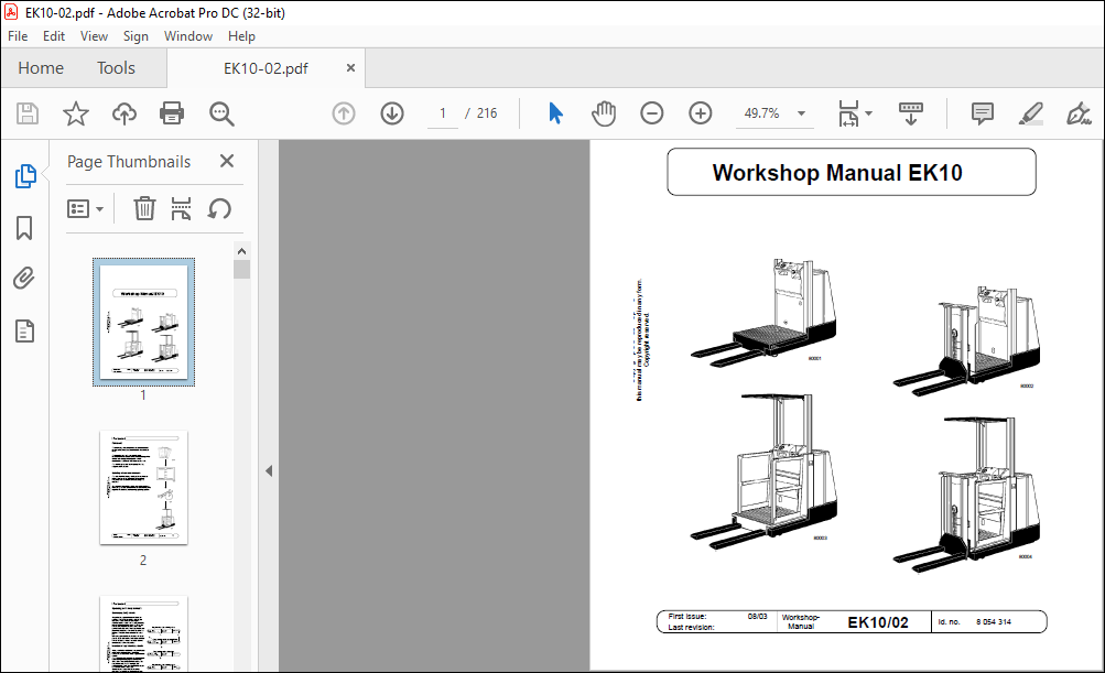
Still EK10 Workshop Manual 8054314 – PDF DOWNLOAD
Still EK10 Workshop Manual 8054314 – PDF DOWNLOAD
IMAGES PREVIEW OF THE MANUAL:

FILE DETAILS:
Still EK10 Workshop Manual 8054314 – PDF DOWNLOAD
Language : English
Pages :216
Downloadable : Yes
File Type : PDF
Size:6.24 MB
DESCRIPTION:
Still EK10 Workshop Manual 8054314 – PDF DOWNLOAD
Foreword
- This workshop manual provides specifications and describes functional characteristics of the standard truck.
- This provides you with a comprehensive documentation to ensure better understanding of the vehicle technology and so permit correct maintenance and repair work to be carried out. The workshop manual is always updated by supplementary sheets.
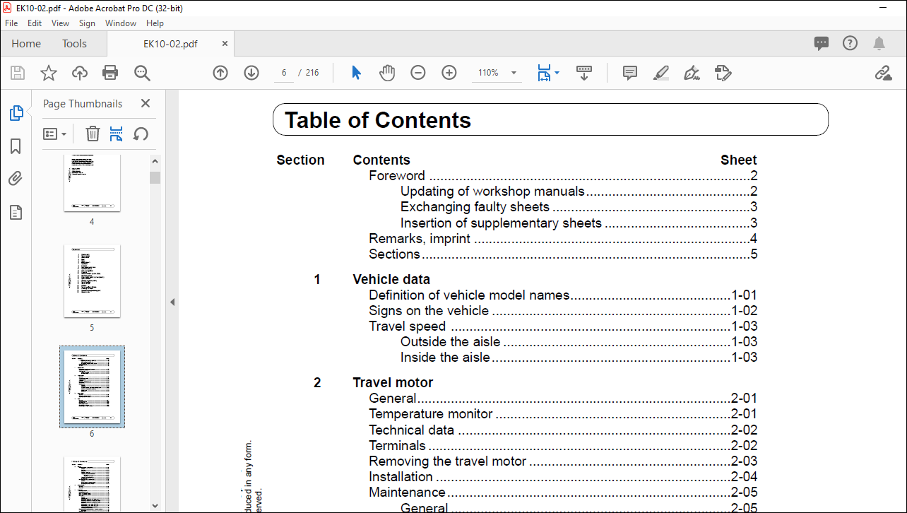
TABLE OF CONTENTS:
Still EK10 Workshop Manual 8054314 – PDF DOWNLOAD
Section Contents Sheet
Foreword 2
Updating of workshop manuals 2
Exchanging faulty sheets 3
Insertion of supplementary sheets 3
Remarks, imprint 4
Sections 5
1 Vehicle data
Definition of vehicle model names 1-01
Signs on the vehicle 1-02
Travel speed 1-03
Outside the aisle 1-03
Inside the aisle 1-03
2 Travel motor
General 2-01
Temperature monitor 2-01
Technical data 2-02
Terminals 2-02
Removing the travel motor 2-03
Installation 2-04
Maintenance 2-05
General 2-05
Cleaning 2-05
Visual inspection, replacing damaged parts 2-06
Checking the brush mechanism 2-08
Commutator 2-09
Bearings 2-09
3 Drive wheel
General 3-01
Removing the drive wheel 3-01
Installing the drive wheel 3-01
4 Gear
Remove 4-01
Installing the gear 4-02
Changing oil 4-03
Oil change method 4-04
Checking the oil level 4-05
Lubricating the bogie bearing 4-05
Brake
Electromagnetic spring brake 5-01
General 5-01
Function 5-02
Removal 5-03
Checking the rotor 5-03
Adjusting the brake clearance 5-04
General 5-04
Adjustment process 5-04
Adjusting the braking force 5-05
Maintenance 5-06
Measuring the brake deceleration 5-07
General 5-07
Preparations for measurement 5-07
Evaluating the measurement 5-08
6 Idling wheels
General 6-01
Removal 6-01
7 Hydraulic
Montagevorschrift 7-01
Hydraulic circuit plan 7-01
Block diagram for NO/HO 7-02
Block diagram for NM/HM 7-03
Pump unit 7-04
General 7-04
Components: 7-04
Electrically releasable non-return valve 7-05
Replacing the carbon brushes (NO, NM) 7-06
Replacing the carbon brushes (HO, HM) 7-07
Removal 7-08
Removing the pump motor (NO, NM) 7-09
Removing the pump motor (HO, HM) 7-10
Adjustment Pressure release valve 7-11
Changing the hydraulic oil 7-12
Bleeding the lift cylinders and the hydraulic system 7-13
Procedure 7-13
Distributor block 7-14
Bubble reservoir 7-15
Hydraulic hoses 7-16
Section Contents Sheet
8 Cylinders
Cylinder support 8-01
Main lift cylinder on NO/NM 8-02
Removal 8-02
Dismantling 8-03
Main lift cylinder on HO/HM 8-04
Removal 8-04
Dismantling 8-05
Additional lift cylinder on NM/HM 8-06
Removal 8-06
Dismantling 8-07
9 Line break protection
General 9-01
10 Hydraulic pump
General 10-01
Removing 10-02
Dismantling 10-03
11 Aisle recognition
General 11-01
12 Steering
Block diagram of the steering system 12-01
Pin assignment 12-02
Setpoint potentiometer, steering wheel 12-04
Replacing 12-04
Setpoint potentiometer, steering knob 12-05
Replacing 12-05
Actual value potentiometer 12-06
Replacing 12-06
Quick start 12-07
Travel on curves function 12-08
Steering lock 12-09
13 Vehicle control system (FZS)
General 13-01
Location 13-01
Identification 13-01
Technical data 13-01
Guide to versions 13-02
Pin assignment 13-03
Input/output assignment 13-06
13 Vehicle control system
Error diagnosis 13-07
Flashing code, FZS2 13-07
Table of functions, FZS2 13-08
Application 13-08
Pedestrian operating mode 13-09
Switch-over, 2nd operating console 13-10
Power outputs 13-11
Travel enable 13-12
14 Operating console
Position of the operating elements 14-01
Removal 14-01
Installing 14-01
Wheel position display 14-02
Adjustment 14-02
Teaching in the FZS2 14-02
2nd operating console 14-03
Pedestrian operating mode 14-04
15 End-of-aisle safety system (EASS)
End-of-aisle safety system (EASS) 15-01
General 15-01
EASS Universal 15-02
Error codes 15-03
EASS Inductive 15-04
Function 15-04
Guide to the system 15-06
Monitoring 15-07
Mounting the proximity switches 15-08
Testing the proximity switches 15-08
Displays and pin assignment 15-09
EASS Magnetic (bistable) 15-10
Function 15-10
Guide to the system 15-12
Monitoring 15-13
Magnetic switch 15-14
Description 15-14
Bistable action 15-14
Switching magnet 15-15
Description 15-15
Handling instructions 15-15
Displays and pin assignment 15-16
16 Speed sensor
General 16-01
Terminals block connector X2 16-01
Signal sequence 16-01
Testing the speed sensor 16-02
17 ABÜ – Braking monitor
Block diagram 17-01
Pin assignment 17-02
General 17-04
Functions 17-05
Travel on curves 17-05
Signal adaptation 17-05
Flashing error codes 17-06
18 Travel control
Block diagram for “Travel” 18-01
General 18-02
Main current section – terminals 18-03
Pin assignment 18-04
Description of functions 18-07
Braking modes 18-07
Table of operating modes 18-07
Hour meter 18-08
Service hour meter 18-08
Battery discharge indicator 18-08
Monitoring function 18-09
Error display 18-10
Test procedure 18-10
19 Direction sender
General 19-01
Replacing 19-01
20 BDI/HM
General 20-01
Pin assignment 20-02
Function 20-03
Error display 20-03
Battery discharge indicator 20-03
Hour meter 20-04
Contents Sheet
21 Travel control software
General 21-01
Making a connection 21-01
Setting parameters 21-02
Test 21-03
Diagnosis 21-03
“File” menu 21-03
Summary of the most important parameters 21-05
Battery discharge curves 21-06
List of parameters 21-07
Description of parameters 21-12
Errors displayed with flashing code 21-17
List of error codes 21-18
Tester Table 21-19
22 Steering software
General 22-01
Making a connection 22-02
Errors 22-03
Current errors 22-03
Stored errors 22-03
Teaching in 22-04
General 22-04
Procedure 22-04
Setpoint potentiometer 22-05
Actual value potentiometer 22-06
Tester 22-09
Speed measurement 22-09
Amplifier data 22-10
Digital inputs and outputs 22-11
Travel on curves active 22-11
Deadman 22-11
Steering wheel/ -knob 22-11
Steering OK 22-11
Steering motor contactor 22-12
Safety relay 22-12
Potentiometer voltages 22-13
Supply voltage of actual and setpoint values 22-13
Setpoint voltage at the steering wheel 22-13
Actual value voltages at the drive wheel 22-13
Table of errors 22-14
Hand-held programming unit
General 23-01
Operating elements 23-01
Switching on 23-02
Switching off 23-02
Language selection 23-03
Setting parameters 23-04
PROGRAM menu 23-04
Function 23-05
Special program menu 23-06
Resetting to initial settings 23-07
Loading settings from the control system
into the programming unit 23-08
Loading settings from the programming unit
into the control system 23-09
Deleting the diagnosis data 23-10
Adjusting the display contrast 23-11
Language selection 23-12
Displaying information about the programming unit 23-12
Displaying information about the control 23-12
Test menu 23-13
Displaying current errors 23-14
Error history 23-14
More products