$33
STILL STED Diesel LPG forklift trucks RX70-16 RX70-18 RX70-20 workshop Manual – PDF DOWNLOAD
STILL STED Diesel LPG forklift trucks RX70-16 RX70-18 RX70-20 workshop Manual – PDF DOWNLOAD
FILE DETAILS:
STILL STED Diesel LPG Forklift Trucks RX70-16 RX70-18 RX70-20 Workshop Manual – PDF DOWNLOAD
Language : English
Pages : 372
Downloadable : Yes
File Type : PDF
DESCRIPTION:
STILL STED Diesel LPG Forklift Trucks RX70-16 RX70-18 RX70-20 Workshop Manual – PDF DOWNLOAD
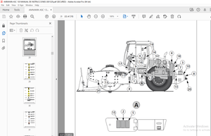
Special featuresThe type carriers described belong to the RX series. A few units with a high proportion of common parts make up many different trucks of different versions.New in this series:• Ergonomic driver’s workplace Generation 2 mini-lever Generation 2 display operating unit• Diesel-electric drive with three-phase AC technology Closed-loop AC drive technology Intelligent drive management for very low consumption Hydraulic fans and exhaust system with new air cooling duct• Blue-Q Characteristic curve optimisation of the drive The following can be parameterised switching off auxiliary consumers and enabling the consumption display• Removable diesel tank on the counterweight Brake resistor integrated in the radiator• Air filter integrated in the inverter housing
IMAGES PREVIEW OF THE MANUAL:


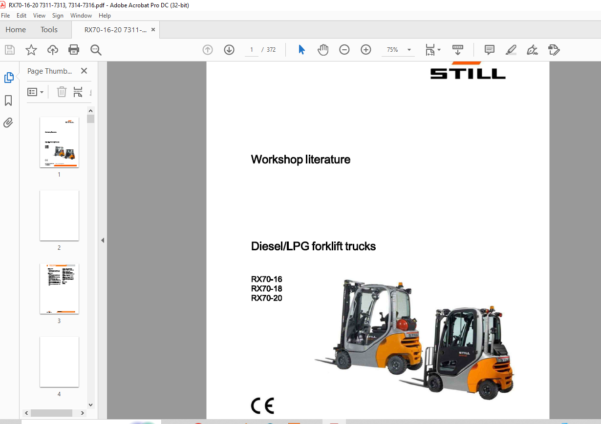
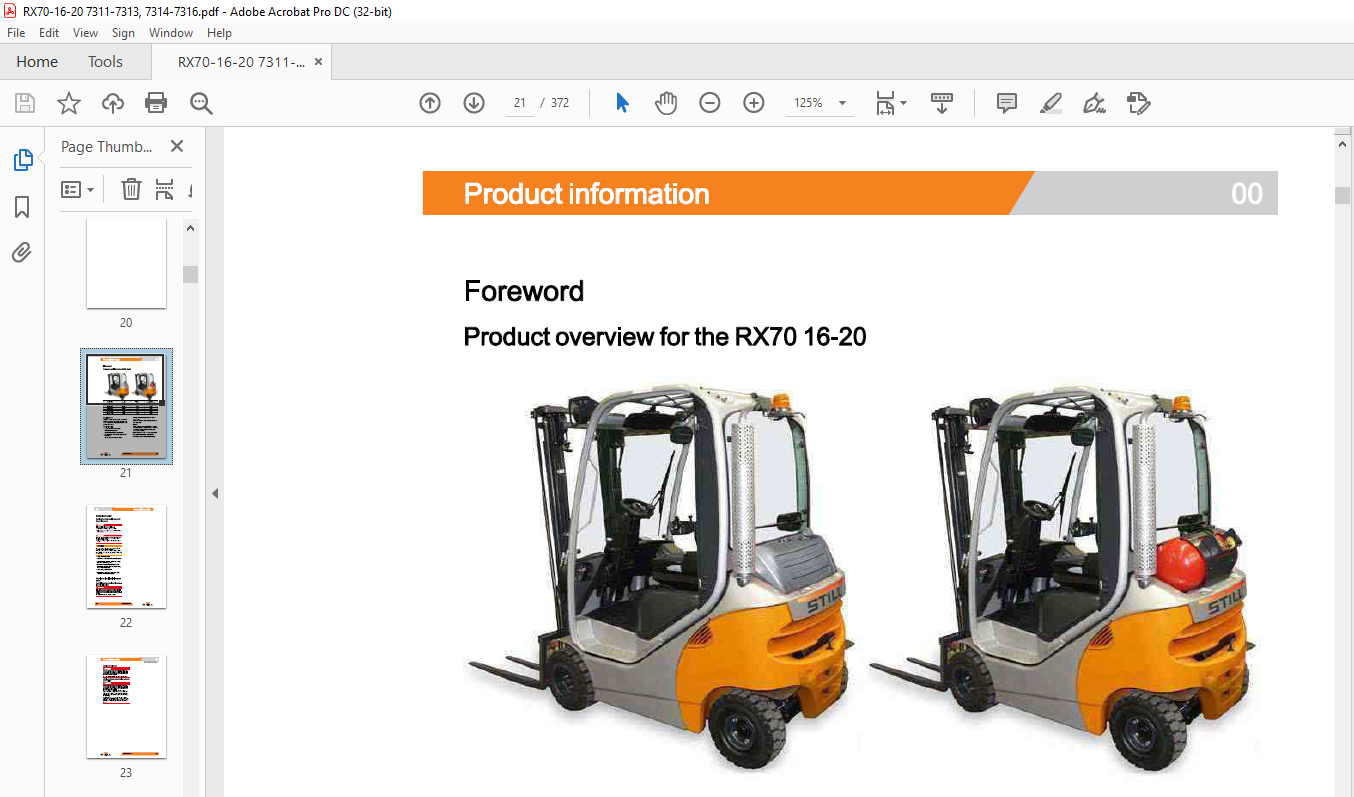


TABLE OF CONTENTS:
STILL STED Diesel LPG Forklift Trucks RX70-16 RX70-18 RX70-20 Workshop Manual – PDF DOWNLOAD
00 Product Information
Foreword
Product overview for the RX70 16-20
Safety Information
Parking the truck so is secured for service work
Working on Ive electrical components
Working on the LPG system
Securing the fork carriage
01 Service
Maintenance
Maintenance Instructions
Maintenance-1000 hours/annually
Maintenance-3000 hours/every two years
Operating materials
Measuring and testing equipment
Special tool
Hamesses and holsts
Standardised lightening torques for standard-pich threads and fine-lich threads
Standardised lightening torques for hose fittings
02 Diagnostics
Introduction to DiaMon
STEDS-Navigator
CAN box diagnostics
Diagnostic set-up
Staring DiaMon
Working with DiaMon
Reading out and clearing the erroret
Reading out access codes
Working using the ABE
Read error st Clearing orrorists
11 Electric motor
Traction motor
General techalcal data
Sectrical connections
Drive unit
Rev sensor
Pin sensor
Temperature sensor
Temperature sensor KTY84
Generator
General technical data
Generator
Removing and Instal ng the generator
12 Internal combustion engine
Internal combustion engine
Engine unk
Engine unit Removal and Installation
Starter motor
Starter ring gear
Alternator monitoring
Retrofitting the 110-Aerator for TCU 1
Diesel engine
SDI generall technical data
VW-Diesel engine
Engine control un ECU-two-part
LPG engine
LPG general technical data
VW LPG-2.0 Bre B
Engine control un ECU
13 Internal combustion engine-attachment parts
Air Intake/filer
Air Intake
Air filter
Cooling system
Cooling drou
Coolant
Checking, topping up and changing the coolant Radiator system
Radiator Removal and Installation
Fan Impeller-fan motor
Diesel fuel system
Fuel system
Fuel filter
Low fuel warning threshold
LPG system
LPG system
Impoo components
Evaporator function-gas mixer
Suction module
MAPIMAT sensor 088
Chassis module
Actuator un
Gas shut-off valve unit
Gas shut-off valve monitoring Shut-down due to lack of gas
Maintenance and test specifications
Testing for leaks in the LPG system
Testing CO level in exhaust gases
Servicing the LPG ther
Servicing the 30-bar high-pressure relief valve
Evaporator-maintenance
Safety valve-1.7 bar
LPG cylindertank
LPG cylinder
14 Internal combustion engine-exhaust system
Exhaust system-diesel
Exhaust system
Exhaust system-particle filter
Generall technical data-Eberspächer
Eberspächer particle for
7.5kW■berspächer particle fiber Regeneration
Maintenance Instructions
Exhaust system-LPG
Lambda control system
Lambda sensor
Three-way catalytic converter
22 Mechanical drive axle
Drive aude AD20-02
General technical data
Drive axde
Removal Installation of the drive ande
Drive wheel unit
Removal Installation of the drive wheel unit
Repairing the drive wheel un
Traction motor
Service brake
Gearbox o
31 Chassis
Counterweight Counterweight
34 Driver’s place
Bonnet-cover-Insulation
Bonnet
42 Steering system
Hydraulic steering
General technical data
Steering system
Steering-error detection
Steering unk
Priority valve
Steering wheel and steering column
Steering column
Steering axde
General technical data, swing ade
Swing exe
Swing axe Removal and Installation
Wheel hub
Steering angle
Tie rod
Axle stub
49 Brake system
Mechanical service brake
Brake sensor 182
Changing the brake cable Service brake
Parking brake
Changing the brake cable for the handbrake
Actuating force of the handbrake
Parking brake switch 183
50 Controls
Single pedal
Accelerator-single-pedal
Dual pedal
Accelerator-dual-pedal 2nd generaton
Controls
Joystick 4Plus
Axle assignment-Joystick 4Plus
Joystick
Joystick operation
Generation 2 minHover
Generation 2 minHoverActuation
Tip switch
Generation 1 minHover
Axle assignment
56 Display elements
Operating console
Direction Indicator module (Fall)
Display screen
Display and operating unit, generation 2 (ABE2)
ABE 2 Instalation and removal
CPP 28
Soot CPP (CPP5)
Relay Power-Port
64 Electronic controls
Traction hydraulics and working hydraulics control
Truck Control Un (TCU)
TCU, generation 2 (TCU2)
Truck Control Unit (TCU) Removal and Instalation
Inverter
Inverter
Inverter Removal and Instalation
Brake resistor
69 Battery and accessories
Starter battery Starter battery
70 Hydraulics
General
General technical data
Depressurising the hydraulics
Liting operating speeds
Ting operating speed
Lowering operating speeds
Safety check
Forward
safely beat
Lowering safety test
Safety checks of hose assembly
Basic hydraulics
Basic hydrauca
Fan motor
Steering hydraulics
Worlding hydraulics
Hydraulic pump
Hydraulic pump Removal and Installation
Hydraulico
Breather for Intake fler
High-pressure her
Conical nipplefings (CNF)
Bolted joint
71 Working hydraulics
Tcy nders
Mast
Tit cylinder Removal and Installation
Changing the set of seals (1500-2000 kg)
Auxary hydraulics
Attachments
Second operating function for attachments
76 Valves
Servo hydraulics
General technical data
Valve block components
Valve block Removal and Installation
Directional control valve block
Directional control valve function, ing Directional control valve function, lowering
80 Load Ift system
Mast bearings
Mast bearings, 1.01-201
81 Lift masts
Liftmast
General technical data
Hose safety valve of triplexx mast
Support roerplay (108/117/130) Load chains-Checking and caring Run-out barler
Worlding on it masts
Liftmast-removal
Liftmast-Installation
Telescopic lit mast
Telescopic
mast (108/117/130)
Adjusting the load chains Telescopic mast (108/117/130)
NIHot mast
Hot mast (108/117/130)
Adjusting the load chains Hot mast (108/117/130)
Triplext mast
Triplet mast (108/117/130)
Removing the support rollers In the It mast
Assembling the it mast after replacing the support rollers
Outer load chains and chain rollers
Middle load chain and chain roer
Adjusting the outer load chains Tilemast (108/117/130) Adjusting the middle load chain Triplet mast (108/117/130)
Lift cylinder
Ut jack
Working on it cyinders
Outer cylinder
Disassembling/assembling the outer cylinder
Centre cylinder
Disassembling/assembling the middle cylinder
End pollon damping of outer cylinder
Middle cylinder end dampener
84 Load support
Fork carriage
Fork canlage
Annex
X Circuit diagrams
Hydraulics
Servo hydraulics
More products