$33
Still STED Electric Pallet Stacker ECV10C-10 ECV10iC-10 ECV10-10 Workshop Manual – PDF DOWNLOAD
Still STED Electric Pallet Stacker ECV10C-10 ECV10iC-10 ECV10-10 Workshop Manual – PDF DOWNLOAD
FILE DETAILS:
Still STED Electric Pallet Stacker ECV10C-10 ECV10iC-10 ECV10-10 Workshop Manual – PDF DOWNLOAD
Language : English
Pages :112
Downloadable : Yes
File Type : PDF
DESCRIPTION:
Still STED Electric Pallet Stacker ECV10C-10 ECV10iC-10 ECV10-10 Workshop Manual – PDF DOWNLOAD
Overview and Specifications
SAFETY WARNING
- For your own safety and that of others, please observe the following safety instructions:
- Thorough and normative maintenance is one of the most important prerequisites to ensure stable and reliable operation of truck. Neglecting regular maintenance could easily lead to the truck malfunction and failure, and potential threats to staff and operational safety.
- Therefore, there must be adequate maintenance equipment, professional maintenance personnel and a comprehensive maintenance plan in place.
NOTE
Please perform the maintenance and inspections according to the following provisions: To strictly enforce the truck maintenance, lubrication and inspection plans. Truck maintenance, lubrication and inspection personnel must be approved by accredited certification or evaluation agency.
The following operations shall be performed
before you leave the truck:
• No parking on slopes.
• Fully lower the forks.
• Cut off the power supply.
• Turn the switch lock to “STOP” and remove the
key.
Prior to truck maintenance:
• Raise the drive wheel off the ground, or cut off
the power supply connection .
• Use wooden wedges orothereffectivefixtures• When performing maintenance underneath
the vehicle, make sure that the lifting device or
jack leg is secure.
• Park your vehicle in a safe and secure area.
IMAGES PREVIEW OF THE MANUAL:
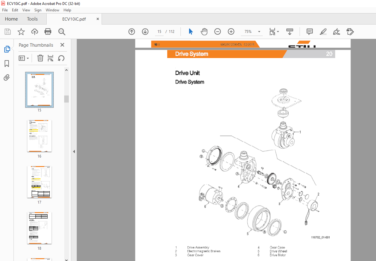
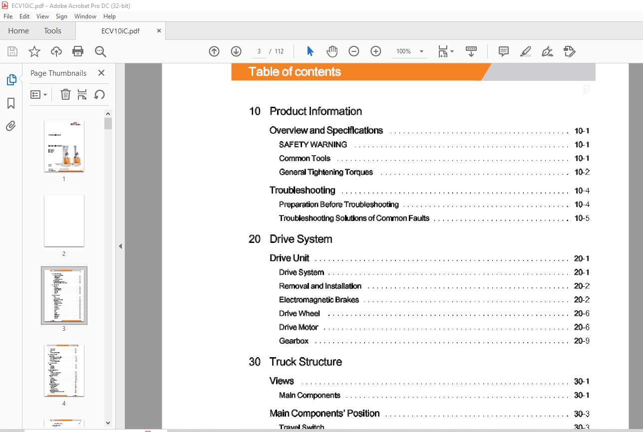
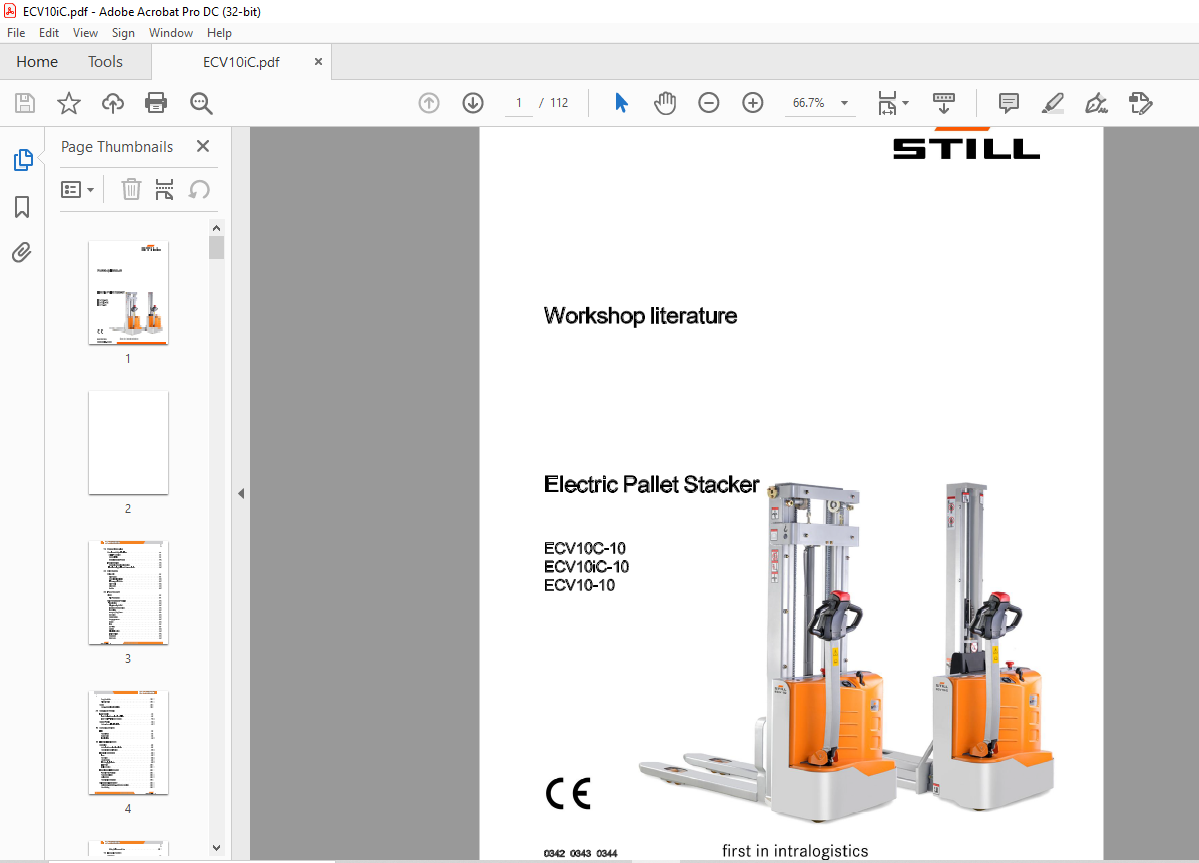
TABLE OF CONTENTS:
Still STED Electric Pallet Stacker ECV10C-10 ECV10iC-10 ECV10-10 Workshop Manual – PDF DOWNLOAD
10 Product Information
Overview and Specifications 10-1
SAFETYWARNING 10-1
Common Tools 10-1
General Tightening Torques 10-2
Troubleshooting 10-4
Preparation Before Troubleshooting 10-4
Troubleshooting Solutions of Common Faults 10-5
20 Drive System
Drive Unit 20-1
Drive System 20-1
Removal and Installation 20-2
Electromagnetic Brakes 20-2
Drive Wheel 20-6
Drive Motor 20-6
Gearbox 20-9
30 Truck Structure
Views 30-1
Main Components 30-1
Main Components’ Position 30-3
Travel Switch 30-3
Lifting/Lowering Switch 30-3
Emergency Reverse Switch 30-4
Hom Switch 30-4
Emergency Stop Switch 30-5
Key Switch 30-5
Charge Gauge 30-6
Charging Indicator 30-6
Buzzer 30-6
Fuse 30-7
Controller 30-7
Charger 30-8
Lifting Limit Switch 30-8
lnter1ock Switch 30-9
Pump Motor 30-9
Gear Pump 30-9
–·· 50028012000 EN -02/2018
Table of contents
Pump Contactor 30-1 O
Solenoid Valve 30-1 O
Cover 30-11
Cover- Removal and Installation 30-11
40 Steering & Wheels
Load Wheels 40-1
Load Wheels – Removal and Installation 40-1
Load Wheels- Faults and Causes 40-2
Castor Wheels 40-3
Caster – Removal and Installation 40-3
50 Operating Devices
Tiller 50-1
Control Lever
Button Switch
Travel Switch
Controller 60-1
Controller- Removal and Installation 60-1
Controller Interface Function 60-2
Electrical Components 60-4
Fuse 60-4
Key Switch 60-6
Charge Gauge 60-7
LED Charging Indicator 60-9
Limit Switch 60-11
Interlock Switch 60-15
Hand Diagnostic Instrument 60-17
Handheld Unit (Optional) 60-17
Parameter Settings 60-18
Monitor Menu 60-20
Controller Error Message 60-21
Maintenance Free Battery 60-23
Maintenance-free Battery- Safety and Warnings 60-23
Use of Battery 60-23
50028012000 EN -02/2018 –··
Table of contents
Battery Maintenance & Care 60-24
70 Hydraulic System
Summary 10-1
Hydraulic Overview 70-1
Pump and Motor Assembly 70-2
Hydraulic Troubleshooting 70-4
Hydraulic Parts 70-6
Pump Motor 70-6
Pump Contactor 70-8
Solenoid Valve 70-10
Reach Cylinder 70-12
80 Mast
Mono Mast 80-1
Lifting Chain 80-1
Lift Cylinder 80-3
Two-stage Mast 80-5
Lifting Chains 80-5
Lifting Cylinder 80-8
Annex
90 Schematic Diagram
Wire Diagram 90-1
Wire Diagram 1 90-1
Wire Diagram 2 90-3
Harness Diagram 90-4
Hydraulic Diagram 90-6
Hydraulic Diagram 90-6
Brake Diagram
Brake Principle
More products