$33
STILL STED Electric Pallet Truck ECH12-12 Workshop Manual – PDF DOWNLOAD
STILL STED Electric Pallet Truck ECH12-12 Workshop Manual – PDF DOWNLOAD
FILE DETAILS:
STILL STED Electric Pallet Truck ECH12-12 Workshop Manual – PDF DOWNLOAD
Language : English
Pages : 106
Downloadable : Yes
File Type : PDF
DESCRIPTION:
STILL STED Electric Pallet Truck ECH12-12 Workshop Manual – PDF DOWNLOAD
Maintenance
Overview
Only by performing regular vehicle maintenance and repair, can ensure the continuous and reliable use of the truck.
Only specially trained and qualified personnel are capable of maintenance and repair operations of the equipment. If you want to perform the maintenance and repair on your own, it is recommended that on-site training should be conducted to your maintenance personnel by the service representative of the vendor.
Working conditions:
- – Truck must be parked on the level ground reserved for maintenance (such area needs to be clean and with less dust), block the wheels with wooden wedges, disconnect the key switch and disconnect the battery connections.
- – When lifting the truck, the lifting tools can only be installed on the fixed positions as specified.
- – When jacking up the truck, appropriate tools, such as wedge blocks, wooden blocks, and so on, must be used to secure the truck to prevent the occurrence of accidental rolling or tipping over.
IMAGES PREVIEW OF THE MANUAL:
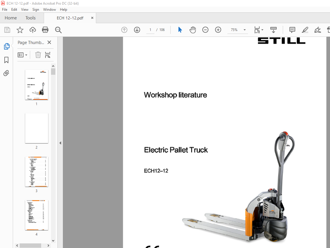
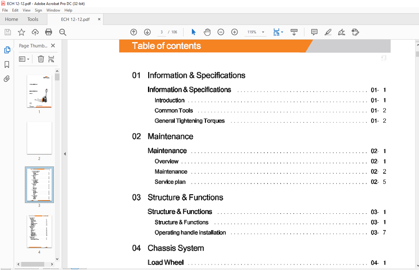
TABLE OF CONTENTS:
STILL STED Electric Pallet Truck ECH12-12 Workshop Manual – PDF DOWNLOAD
01 Information & Specifications
Information & Specifications 01- 1
Introduction 01- 1
Common Tools 01- 2
General Tightening Torques 01- 2
02 Maintenance
Maintenance 02- 1
Overview 02- 1
Maintenance 02- 2
Service plan 02- 5
03 Structure & Functions
Structure & Functions 03- 1
Structure & Functions 03- 1
Operating handle installation 03- 7
04 Chassis System
Load Wheel 04- 1
Load Wheel 04- 1
Cover 04- 3
Cover 04- 3
Lifting Mechanism 04- 4
Lifting Mechanism 04- 4
05 Drive System
Drive System os- 1
Drive Assembly 05- 1
Electromagnetic Brakes 05- 3
Drive Wheel 05- 7
Drive Motor 05- 8
Gearbox 05- 11
06 Operating System
Operating System 06- 1
Control Lever
Button Switch
Travel Switch
Table of contents
07 Hydraulic System
Hydraulic System 07- 1
Hydraulic System 07- 1
Pump and Motor Assembly 07- 4
Manual drop wire adjustment 07- 6
Pump Motor 07- 7
Pump Contactor 07- 9
Solenoid Valve(Electrical Lowering) 07- 12
Reach Cylinder 07- 14
Hydraulic Troubleshooting 07-18
Hydraulic Symbol 07-19
08 Electrical System
Electrical System 08- 1
Controller 08- 1
Key Switch 08- 4
Emergency Stop Switch 08- 5
Inductive Switch 08- 7
Battery • • • • • • • • • • 08-10
Mini Instrument 08-12
Handheld Unit (Optional) 08-17
Controller Error Message 08-19
Electrical Schematic Diagrams 08-23
Cable Wiring Diagrams 08-25
Wiring Harness and Connectors 08-26
09 Trouble Shooting
Trouble Shooting 09- 1
Preparation Before Troubleshooting 09- 1
Troubleshooting Solutions of Common Faults 09- 1
More products