$30
Still STED Electric Pallet Truck EGV-S EGV-S LB Workshop Manual – PDF DOWNLOAD
Still STED Electric Pallet Truck EGV-S EGV-S LB Workshop Manual – PDF DOWNLOAD
FILE DETAILS:
Still STED Electric Pallet Truck EGV-S EGV-S LB Workshop Manual – PDF DOWNLOAD
Language : English
Pages : 236
Downloadable : Yes
File Type : PDF
DESCRIPTION:
Still STED Electric Pallet Truck EGV-S EGV-S LB Workshop Manual – PDF DOWNLOAD
General information
Safety precautions
Description of safety symbols
This document gives the danger wamings Each of such danger warnings consists of a graphic symbol, followed by a description of the danger and its consequences, and the description of how it can be avoided. The types of wamings used are described below
Safety precautions
- When topping up the operating materials, only clean containers should be used. Follow the manufacturer’s safety and disposal instructions regarding the operating and cleaning materials.
- Do not disperse oils or other operating liquids! Any spilt liquid must be immediately collected and neutralised with a binding material (such as an oil binder) and then disposed of in accordance with current regulations.
- Always comply with anti-pollution regulations! Before carrying out work that involves lubrication, filter replacement or hydraulic equipment inter- ventions, the area in question must be thoroughly cleaned. The replaced parts must always be disposed of in accordance with the anti-pollution laws.
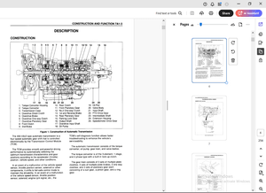
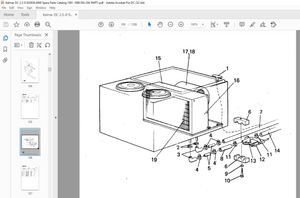
IMAGES PREVIEW OF THE MANUAL:


TABLE OF CONTENTS:
Still STED Electric Pallet Truck EGV-S EGV-S LB Workshop Manual – PDF DOWNLOAD
00 General Information
Safety precautions
Description of safety symbols
Preminary maintenance operations
To avold accidents
Safety Regulations Relative to Operating Materials
Product Information
Frame Jabeng
Stopping the truck In an emergency
Type of truck use of versions with straddles Indalfunction
Fork Use In Cold-Storage Rooms.
Using the truck with extension leads
Maintenance
Synopic Table of Maintenance Operations
Supply Table
Tolerance table for force and it mast
Holst verticality tolerance table
Speed tolerance tabo
Table of screws and their respective tightening torques
02 Diagnostics
Truck diagnostics
Connections before running truck diagnostics
Software for truck diagnostics
Bectronic system diagnostics
“PC Console” software
Description of the PC CONSOLE menus
Menu description PARAMETER
Description of the TST R menu
Analog signal acquison (PROGRAM VACC)
Table of parameters
Alarms st
LES steering system diagnostics
“DiaMon-LES” software
Alarme
11 Motor
Traction motor
Drive motor type
Drive disabing
Traction speed
Automatic deceleration when turning
Disassembly and reassembly of the traction motor
Drive unit assembly diagram
Removing the drive motor
22 Reducer
Disassembly and reassembly of the transmission gear
Instructions for assembly/service on the reducer
Reducer gearbox drawing
Description of the reducer
Reducer gearbox group overhaul
Maintaining the reducer
Lubricating the transmission gear
Resetting the reduction gear of level
Adjustment of the bevel gear system
31 Liftmast
Covers
Removing the motor compartment cover
Removing the battery cover
Assembling the casing
Compartment for accessing the battery charger supply cable (fitted)
Movable operator step plate
Stop plate assembly diagram
Removing and fitting the step plate
Stop plate sensors
Movable operator side panels
Side panel assembly diagram Hub torque assembly diagram Removing the side panel assembly
42 Steering Ter
THer head controls
Anti-crush button
Disassembling the or body Terhead potendomater
Disassembling the or assembly Overhauling these rod barrel
Assembling the ter assembly THer cable layout diagram Calibrating the er assembly
Tier operating conditions
Blectric steering
Steering system
Steering motor reducer diagram(before modification)
Disassembling the steering motorun(before modification)
Motor reducer assembly overhaul
Motor reducer pin greasing
Motor reducer diagram (post-modification)
Disassembling the motor reducer assembly(post-modication)
Electrical steering system ca bration
46 Wheels
Drive wheel, pivoting wheels and load rollers
Disassembly and reassembly of the dive whool
Complate pivoting whoal unit
Disassembly and reassembly of the pivoting wheel Load rollers
Removing and assembling the load castors
49 Brake system
Braking method
Braking devices and methods
Electromagnetic brake
ectromagnetic brake assembly diagram
Steps for assembling the electromagnetic brake
Calibration of the electromagnetic brake
60 Electrical and electronic system
Bectrical/electronic system: general information.
Funcional diagram
Changing fuses
Sleeves and connectors
COMBI system
Technical features of the electronic system
List of electronic system Input/output functions
Batteries and battery charger
Battery size and weight (for models without straddles
al function)
Battery size and weight (for models with straddles Inalt function)
Battery status Indicator and hour meter
Battery Recharging
Recharging the battery using the on-board battery charger (optional) Battery connectors (socket and plug)
Changing the battery (for models without straddles Inlet function)
Changing the battery (for models with straddles
71 Hydraulic components
function)
Hydraulic control unit
2,2 kW/24V controller: for model without straddles Intfunction
3 kW/24V controller: for model without straddles In
24V, 3 kW controller for modells with straddles Rial
function function
Removing the hydraulic control unit and tank
Tank: all level
Removal of proportional solenoid valve(before modification)
Removal of proportional solenoid valve(post-modification)
Replacing the complete pre-modification control un with the post-modification contro unit
Valve block for emergency lowering(for models with the straddle Indaling func- tion)
Replacing the non-return valve
Forking cylinder
Lift cylinder uniformodels with the straddle function)
Lift cylinder overhaul
Assembling theft cylinder
80 Load Ifting system
Lifting column
Removal and assembly of the ting column
Disassembling and assemb ng column parts
Bleeding cylinders
Adjusting the chains (for models with straddle Inal)
84 Load support system
Fork carriage
Removing and assembling the fork carriage runners
Forks, rods and levers
Removing and Installing the lovers(for models with the straddle Initialing function) Removal and replacement of the bushings
91 Optional
Standard and optional features
Standard and optional features


