$31
STILL STED Forklift CTR250, CPF200 Workshop Manual 127-02 – PDF DOWNLOAD
STILL STED Forklift CTR250, CPF200 Workshop Manual 127-02 – PDF DOWNLOAD
FILE DETAILS:
STILL STED Forklift CTR250, CPF200 Workshop Manual 127-02 – PDF DOWNLOAD
Language : English
Pages : 184
Downloadable : Yes
File Type : PDF
DESCRIPTION:
STILL STED Forklift CTR250, CPF200 Workshop Manual 127-02 – PDF DOWNLOAD
Safety
Maintenance safety guidelines
No changes, modifications or additions may be made to the tractor without approval from the manufacturer
► Before attempting any repairwork, apply the parking brake, turn the keyswitch off, disconnect the battery, and, unless the particular routine being performed requires otherwise, chock the wheels securely front and rear.► Before carrying out any electrical maintenance or checks, raise the drive wheels clear of the ground and securely chock the tractor in position.► Protective equipment i.e. goggles and gloves must be worn at all times when working on batteries.► Take the necessary fire precautions when working on batteries.► Always handle, charge and maintain batteries according to the manufacturer’s instructions supplied with the battery. Workshop literature -127 807 70 01 EN -04/2008 Product information 0► Always ensure any lifting equipment is of sufficient capacity and has the relevant certification. All blocks, jacks and chains etc. are subject to regular examination and must only be used for the purpose intended.► Use only prescribed attachment points when towing or lifting. Attach connections carefully. Check that the pins and/or bolts provided are secure before loading. Never stand close to drawbars, slings or chains that are working under load.► Before disconnecting hydraulic connections, ensure that there is no pressure in the system .► Do not allow hydraulic oil under pressure, for example at a leak, to penetrate the skin. Medical aid is required if such an injury occurs.
IMAGES PREVIEW OF THE MANUAL:

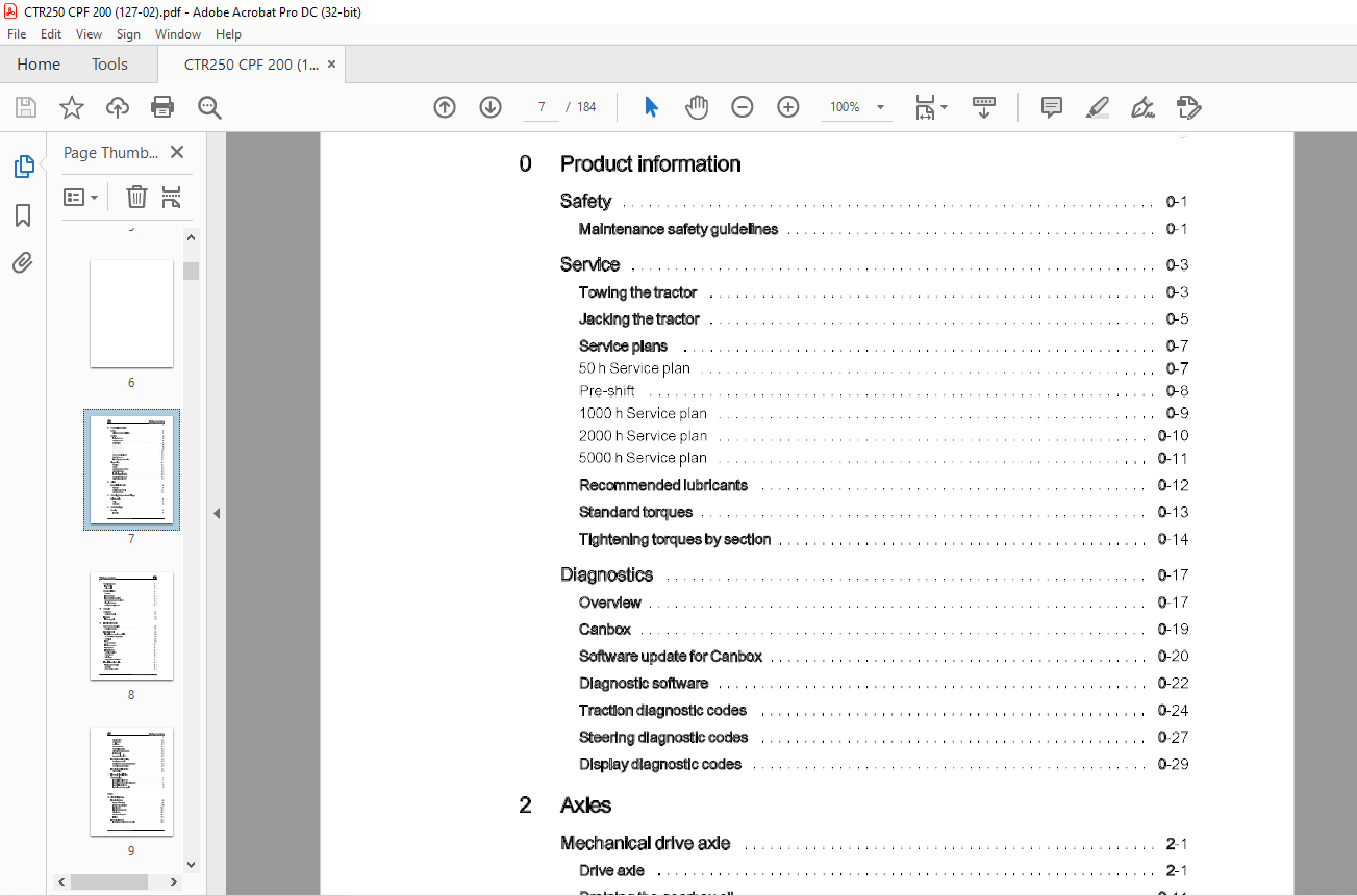
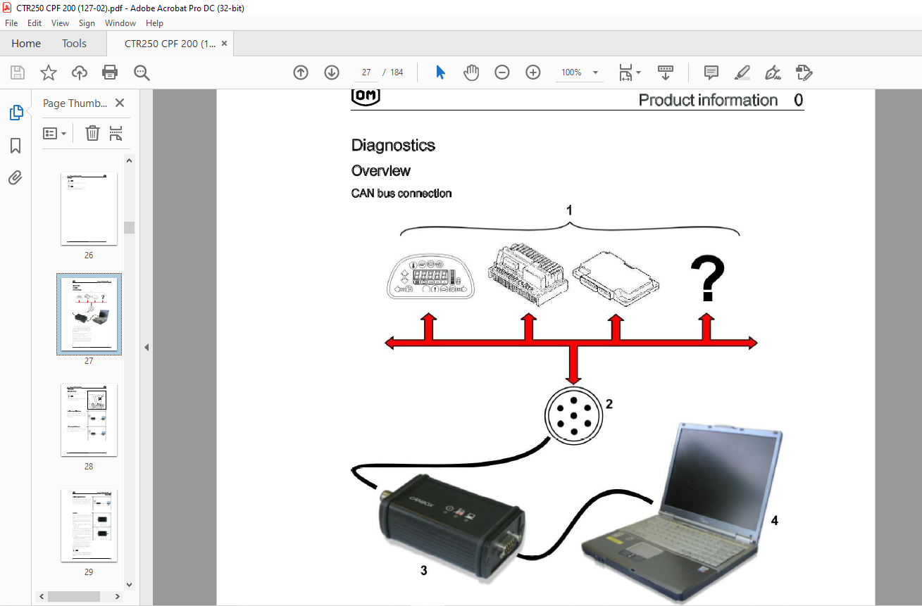
TABLE OF CONTENTS:
STILL STED Forklift CTR250 CPF200 Workshop Manual 127-02 – PDF DOWNLOAD
0 Product information
Safety 0-1
Maintenance safety guidelines 0-1
Service 0-3
Towing the tractor
Jacking the tractor
0-3
0-5
Service plans 0-7
50 h Service plan 0-7
Pre-shift 0-8
1000 h Service plan 0-9
2000 h Service plan 0-10
5000 h Service plan 0-11
Recommended lubricants 0-12
Standard torques 0-13
Tightening torques by section 0-14
Diagnostics 0-17
Overview 0-17
Can box 0-19
Software update for Canbox 0-20
Diagnostic software 0-22
Traction diagnostic codes
Steering diagnostic codes
Display diagnostic codes
2 Axles
Mechanical drive axle 2-1
Drive axle 2-1
Draining the gearbox oil 2-11
Gearbox breathers 2-12
3 Chassis, bodywork and fittings
Driver’s cabin 3-1
Cabin 3-1
Dashboard 3-5
4 Undercarriage
Steering 4-1
Front axle 4-1
Workshop literature -127 807 70 01 EN -04/2008 V
Table of contents
Wheels and tyres 4-17
Front wheels
Drive wheels
Brake installation 4-19
Overview 4-19
Front brake pads 4-23
Front brake disc and calliper 4-24
Brake master and servo cylinders 4-25
Bleeding the brakes 4-30
Parking brake adjustment 4-32
5 Controls
Accelerator 5-1
Accelerator pedal 5-1
Footbrake 5-3
Footbrake pedal 5-3
6 Electridelectronic
Battery and accessories 6-1
Removing the battery 6-1
Electrical control 6-3
EMC – Electromagnetic compatibility 6-3
AC Control – operating principle 6-4
Control unit 6-7
Fuses 6-8
DC/DC converters 6-1 0
Lighting converters 6-11
Lighting relays 6-12
Lighting jumpers 6-13
Control module -A2 6-15
Connector X 13 6-16
Switching on 6-19
Charge resistor module -A 11 6-19
Electrical control – traction 6-22
Traction power modules 6-22
Seat switch 6-25
Batterydoorlockswitch 6-26
Workshop literature -127 807 70 01 EN -04/2008
Table of contents
Direction switch 6-27
Parking brake 6-28
Accelerator 6-30
Brake pedal switch 6-32
Regenerative braking 6-33
Drive axle temperature sensor 6-34
Inching control 6-35
Speed reduction switch 6-37
Electrical control – Steering 6-38
Steering power module 6-38
Steering pump motor temperature sensor 6-41
Accumulator pressure switch 6-42
Electrical control – Display 6-43
Driver’s display 6-43
7 Hydraulic installation
Powersteering 7-1
Annex
Hydraulicfilterreplacement 7-1
Hydraulictankbreatherfilterreplacement 7-1
Hydraulic fluid level check 7-2
Hydraulic motor and pump unit 7-3
10 Circuit diagrams
Electric diagrams 10-2
Traction (with inching) 10-2
Traction (without inching) 10-8
Electric heater 1 0-14
Electric heater – keycode 1 0-1 5
Diesel heater 1 0-1 6
Diesel heater – keycode 1 0-1 7
Lighting 10-18
Hydraulic diagrams 10-24
Hydraulic and braking system schematic
More products