$33
STILL STED forklift CX-CXD-CXM KANVAN-CXS CXT-CXH Workshop Manual – PDF DOWNLOAD
STILL STED FORKLIFT CX-CXD-CXM KANVAN -CXS CXT-CXH WORKSHOP MANUAL – PDF DOWNLOAD
FILE DETAILS:
STILL STED forklift CX-CXD-CXM KANVAN -CXS CXT-CXH Workshop Manual – PDF DOWNLOAD
Language : English
Pages : 200
Downloadable : Yes
File Type : PDF
DESCRIPTION:
STILL STED forklift CX-CXD-CXM KANVAN -CXS CXT-CXH Workshop Manual – PDF DOWNLOAD
General product information
Introduction
LayoutThis workshop manual essentially has two parts:
General information on the product, diagnosis
of malfunctions and special tools: Group 0
Repair instructions: Groups 1 to 9
- Each part of the current manual is composed of a set of separate sheets that are led in a STILL binder according to their group number. The manual is organised according to the same rules used for the spare parts catalogue, which is divided into sub-groups (assemblies or construction groups).
- To make it as simple as possible to identify the assemblies presented in this manual, the number of each assembly is printed in the upper right-hand corner of each page. Where necessary, we have included tables to provide the maintenance department with relevant technical data.
- These tables must also be consulted by experienced mechanics. The manual contains a detailed description of truck design features, as well as component and assembly operating features. To supplement the operations described in this manual, comments, instructions and explanatory diagrams have also been provided.
IMAGES PREVIEW OF THE MANUAL:
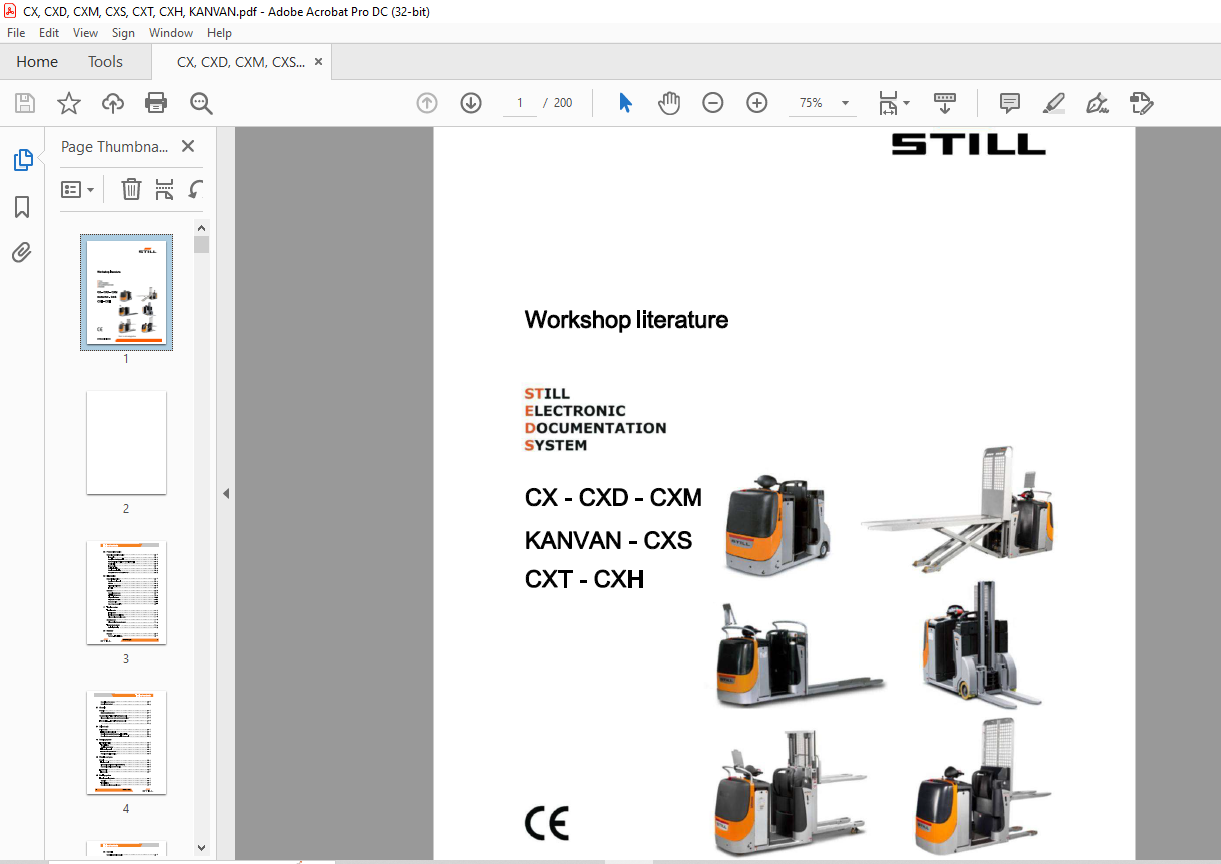
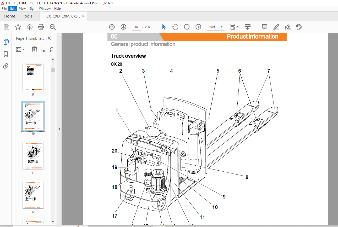
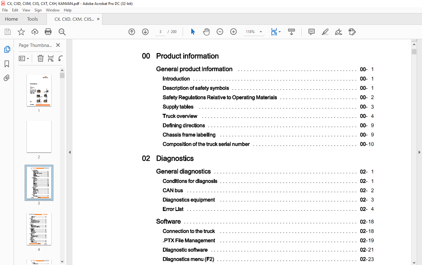
TABLE OF CONTENTS:
STILL STED forklift CX-CXD-CXM KANVAN -CXS CXT-CXH Workshop Manual – PDF DOWNLOAD
00 Product information
General product information 00
Introduction 00
Description of safety symbols 00
Safety Regulations Relative to Operating Materials 00
Supply tables 00
Truck overview 00
Defining directions 00
Chassis frame labelling 00
Composition of the truck serial number 00
02 Diagnostics
General diagnostics 02
Conditions for diagnosis 02
CAN bus 02
Diagnostics equipment 02
Error List 02
Software 02
Connection to the truck 02
PTX File Management 02
Diagnostic software 02
Diagnostics menu (F2) 02
Setup menu (F3) 02
Menu Measurement (F4) 02
11 Traction motor
Traction motor 11
Traction motor 11
Traction motor technical data 11
Disassembling the traction motor 11
Speed sensor 11
Disassembling the speed sensor 11
Temperature sensor 11
Replacing/Checking 11
20 Reducer
Reducer 20
Reducer- Technical data 20
Description of the reducer 20
Removing the reducer 20
31 Chassis
Chassis 31
Motor compartment cover 31
Counterweight- For CXT and Kanvan only 31
Disassembling the rear cover and the counterweight 31
Tow coupling- For CXT and Kanvan only 31
31
34 Driver’s cab
Driver’s seat 34
Folding step plate (optional) 34
Removing the operator’s backrest- For CXT only 34
Removing the operator’s backrest- For Kanvan only 34
42 Steering system
Electrical steering 42
Technical data 42
Steering motor reducer 42
LES steering control 42
Effective value potentiometer 42
Potentiometer pinion bearing 42
46 Wheels and tyres
Wheels 46
Traction wheel 46
Pivot wheels (not fitted to CXT and KANVAN) 46
Rear wheels (CXT and KANVAN only) 46
Load wheels 46
Load wheels 46
49 Braking system
Electric operating brake 49
Operation 49
Technical data 49
Removing the electromagnetic brake 49
50108042301 [EN] III
Table of contents
50 Controls
Cockpit ( control console) 50
Cockpit 50
Cockpit – removal and installation 50
Entering the user code 50
Digicode control 50
Adding the master code 50
Deleting the master code 50
Adding the driver’s code 50
Deleting a driver’s code 50
60 Electronic devices
Electronic components 60
Electrical components and connections 60
Electrical equipment 60
Electronic panel 60
Main contactor 60
Fan 60
Push-buttons 60
Signalling equipment 60
Warning horn 60
Battery and accessories 60
Battery PzS (open-lead) 60
Changing the battery 60
Battery dimensions and weights 60
Sensors 60
Foot interlock pedal 60
Step plate assembly 60
Height sensor 60
64 Electronic controls
Traction controller 64
Removing the traction controller 64
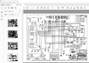
70 Hydraulic system
Hydraulic system – General 70
Hydraulic diagram 70
71 Working hydraulics
Pump unit 71
Technical Data 71
Pump unit 71
Hydraulic oil reservoir 71
Replacing brushes 71
Bearings 71
Disassembly 71
Maintaining the hydraulic system 71
76 Valves
Directional control valve/control valve 76
Lowering solenoid valve 76
80 Load lifting system
Initial lifting device 80
Lift cylinder 80
Mast and fork carriage 80
Servicing the lift cylinder and/or the inner mast 80
Lift mast 80
Disassembly 80
Fork carriage 80
Disassembly 80
Fork arms 80
Disassembly 80
84 Load lifting carriage
Fork carriage 84
Removal of fork carriage and mast CS 1 OM 84
Removing the fork carriage 84
Cylinder 84
Removing the Kanvan
More products