$29
STILL STED Forklift FV-X(12-16) FV-X(12-16)i Workshop Manual – PDF DOWNLOAD
STILL STED Forklift FV-X(12-16) FV-X(12-16)i Workshop Manual – PDF DOWNLOAD
FILE DETAILS:
Still STED Forklift FV-X(12-16) FV-X(12-16)i Workshop Manual – PDF DOWNLOAD
Language : English
Pages : 188
Downloadable : Yes
File Type : PDF
DESCRIPTION:
Still STED Forklift FV-X(12-16) FV-X(12-16)i Workshop Manual – PDF DOWNLOAD
Product information
Instruction and maintenance manual
This chapter gives information taken from the instruction and maintenance manual, considered as of interest for the assistance technician
General Forklift Description This forklift has the following characteristics:
• It is battery powered ;• The driver sits aboard the forklift.• The forklift is a stacker with supporting sidemembers and forks whose arms cover the sidemem bers themselves. In addition to stacking, the version with initial spoke lifting may also be used for handling.• Given its construction, the forklift is used to lift, stack and arrange loads of well defined weight and volume on racks. The version with initial spoke lifting function , the forklift may also be used to handle loads of well defined weight and volume
IMAGES PREVIEW OF THE MANUAL:
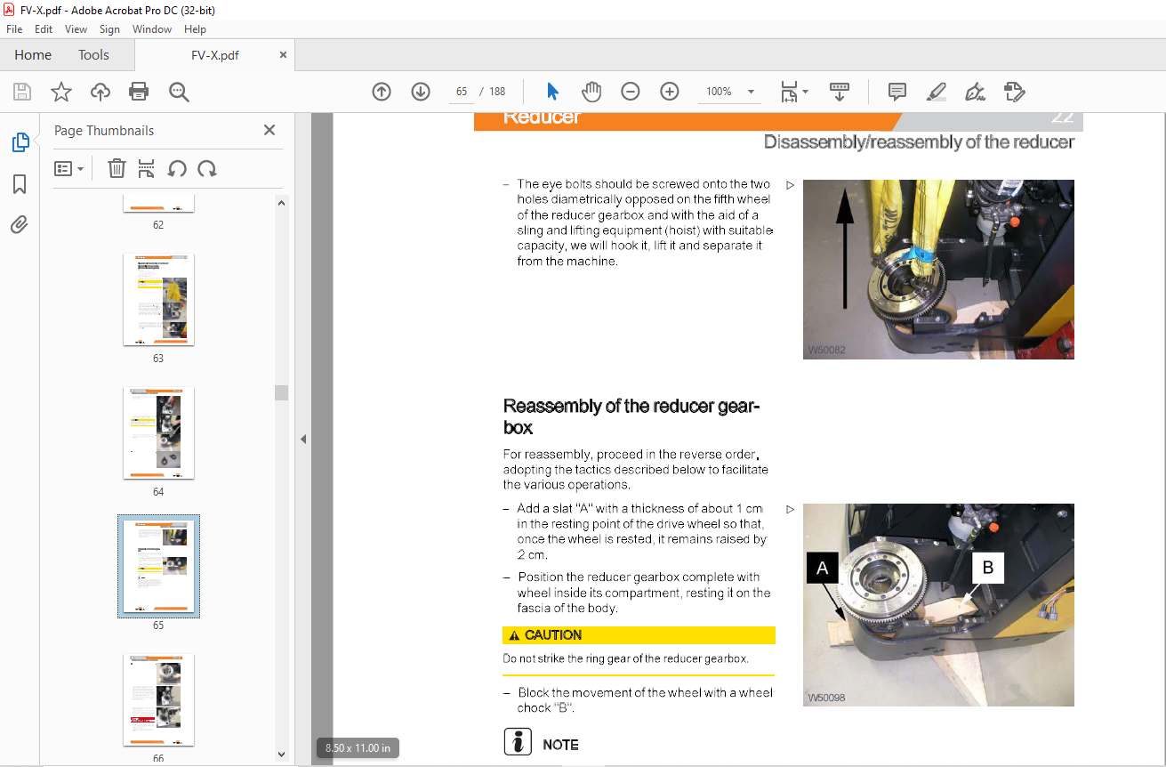
TABLE OF CONTENTS:
Still STED Forklift FV-X(12-16) FV-X(12-16)i Workshop Manual – PDF DOWNLOAD
00 General Information
Product information 00-1
Instruction and maintenance manual 00-1
General Forklift Description 00-1
Definition of direction of travel 00-2
Technical data 00-3
Battery dimensions and weights 00-6
Transporting the truck 00-6
Loading and unloading the truck 00-7
Safety regulations 00-8
Description of safety symbols 00-8
Operations Preliminary to Maintenance 00-8
To avoid accidents 00-8
General Safety Rules 00-8
Safety Regulations Relative to Operating Materials 00-9
01 Service
Maintenance 01-1
General 01-1
SynopticTableofMaintenanceOperations 01-1
Supply Table 01-2
Safetyscrewstighteningtorquetable 01-2
02 Diagnostics
Connectors for diagnostics 02-1
Connectors for diagnostics 02-1
Zapi system diagnostics 02-2
Information aboutthe software 02-2
PC CONSOLE software 02-3
Description of the PC CONSOLE menus 02-5
Menu description PARAMETER 02-10
Description of the TESTER menu 02-14
Traction section parameters (MASTER) 02-16
Pump section parameters (SLAVE) 02-18
Drive section TESTER function (MASTER) 02-20
Pump section TESTER function (SLAVE) 02-21
Standard parameters table 02-22
Drive section alarms (master) 02-25
STILL 45578042305 [EN]
Table of contents
Pump section alanns (slave) 02-28
Analogue signal acquisition 02-31
“LES” electrical drive diagnostics 02-33
Diagnostics by means of PC 02-33
Parameter values 02-35
Alanns 02-35
11 Engine
Drive motor 11-1
Removing the drive motor 11-1
Reassemblyofthedrivemotor 11-2
22 Reducer
Disassembly/reassembly of the reducer 22-1
Disassembly of the anchorage plate and drive reducer gearbox 22-1
Reassembly of the reducer gearbox 22-3
Reducer maintenance 22-7
Description of the reducer 22-7
Instructions for assembly/ service on the reducer 22-7
Adjustment of the bevel gear system 22-8
Reducer section 22-11
31 Truck
Bonnets 31-1
Internal accessibility 31-1
34 Driver’s compartment
II
Seat 34-1
Removalandreassemblyoftheseatandseatsupport 34-1
Step plate 34-3
Platfonn removal procedure 34-3
Platfonn gas spring removal 34-4
Platfonn gas spring disassembly 34-6
Platfonn gas spring refitting 34-6
Mobile platfonn structure removal 34-7
45578042305 [EN] STILL
Table of contents
42 Steering
Electrical steering 42-1
Electric steering system 42-1
LES activation 42-2
Electrical steering system calibration 42-2
Removal and assembly of the steering motor 42-8
Reassemblyofthedrivewheel position potentiometer 42-9
46 Wheels
Wheels 46-1
Access to the drive wheel retaining nuts 46-1
Wheel Tightening Check 46-1
Wheel Wear Check 46-1
Disassembly and reassembly of the traction wheel 46-2
49 Braking
Braking devices and methods 49-1
Removal of the electromagnetic brake; 49-1
Service braking ( eABS) 49-4
Description of service braking (e-ABS) 49-4
Features of the eABS module 49-5
Alarms encoding 49-5
List of alarms 49-6
60 Electrical and electronic system
Electrical/electronic system: general 60-1
COMBI AC1 electronic control functional diagram 60-1
CHARACTERISTICSCOMBIAC1 60-2
COM BI AC1 inputs and outputs 60-4
Removal of the electric panel 60-5
Speed tables 60-8
Wiring 60-9
Changing a fuse 60-9
Power fuse installation 60-1 0
Batteries 60-11
Low battery charge indicator and counter 60-11
Battery replacement 60-12
Stand with lateral battery extraction roller unit ( optional) 60-13
STILL 45578042305 [EN] Ill
Table of contents
Electrolyte Level and Density Check 60-13
Battery Recharging 60-14
71 Hydraulic components
Valve block 71-1
Valve block for versions with initial wheel lifting 71-1
Valve block for versions without initial wheel lifting 71-3
Motor – pump – tank 71-4
Removal and assembly of the tank-pump-motor unit 71-4
80 Lifting
Lift 80-1
Lift assembly 80-1
Mobile structure 80-5
Disassembly of the mobile structure 80-5
Disassembly and reassembly of the lift cylinders 80-8
Adjustment of the guide bearings for the mobile structure 80-11
Replacement of the lift cylinder gaskets 80-13
Maintenanceofthemobilestructureleversystems 80-15
Strut length adjustment 80-18
Annex
A Diagrams
IV
Wiring diagrams A-1
Connection diagram (electrical connection) model with preliminary fork lifting function –
sheet 1/4 A-1
Connection diagram (electrical connection) model with preliminary fork lifting function –
sheet 2/4 A-3
Connection diagram (electrical connection) model with preliminary fork lifting function –
sheet 3/4 A-5
Circuit diagram “Cold storage room version” ( optional) model with preliminary fork lifting
function – sheet 4/4 A-7
Circuit diagram “Fleet Manager” (optional) model with preliminary fork lifting function
A-9
Circuit diagram “PSL keypad-key” ( optional) model with preliminary fork lifting function
A-11
Circuit diagram “Electrical reversed driving “( optional) model with preliminary fork lifting
function A-13
45578042305 [EN] STILL
Table of contents
Circuit diagram ( electrical connection) model without preliminary fork lifting function –
sheet 1/4 A-15
Circuit diagram (electrical connection) model without preliminary fork lifting function –
sheet 2/4 A-17
Circuit diagram ( electrical connection) model without preliminary fork lifting function –
sheet 3/4 A-19
Circuit diagram (electrical connection) model without preliminary fork lifting function –
sheet4/4 A-21
Circuit diagram “Fleet Manager” ( optional) model without preliminary fork lifting A-23
Circuit diagram “Keypad” ( optional) model without preliminary fork lifting function A-25
Circuit diagram “Reversed driving” (optional) model without initial fork lifting function
A-27
Hydraulics diagrams A-29
Hydraulic connection diagram “DPX-TPX lifts” model with preliminary fork lifting function
– sheet 1 /2 A-29
Hydraulic connection diagram “SPX lift” model with preliminary fork lifting function –
sheet 2/2 A-31
Hydraulic connection diagram “DPX – TPX lifts” model without preliminary fork lifting
function – sheet 1/2 A-33
Hydraulic connection diagram “SPX lift” model without preliminary fork lift function –
sheet 2/2 A-35
More products