$20
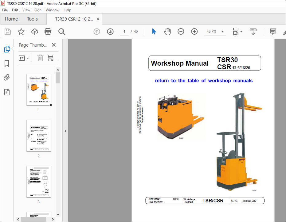
STILL STED Forklift TSR30 CSR 12,5 16 20 Workshop Manual – PDF DOWNLOAD
STILL STED Forklift TSR30 CSR 12,5 16 20 Workshop Manual – PDF DOWNLOAD
FILE DETAILS:
STILL STED Forklift TSR30 CSR 12 5 16 20 Workshop Manual – PDF DOWNLOAD
Language : English
Pages : 40
Downloadable : Yes
File Type : PDF
TABLE OF CONTENTS:
STILL STED Forklift TSR30 CSR 12 5 16 20 Workshop Manual – PDF DOWNLOAD
Section Contents Sheet
Foreword 1
Updating of workshop manuals 1
Exchanging faulty sheets 2
Insertion of supplementary sheets 2
Remarks, imprint 3
Sections 4
Contents 5
1 Vehicle data
Identification 1-01
Signs on the vehicle 1-02
2 Travel motor
General 2-01
Technical Data 2-02
Terminals 2-02
Removing the drive motor 2-03
Replacing the carbon brushes 2-04
Maintenance 2-05
General 2-05
Cleaning 2-05
Visual inspection, replacing damaged parts 2-06
Checking the brush unit,
replacing the carbon brushes 2-07
Commutator 2-08
Bearings 2-08
3 Drive wheel
Replacing 3-01
Removal 3-01
4 Gear
Removing 4-01
Lubricating the bogie bearing 4-02
Changing the gear oil 4-02
Oil change 4-03
Oil change procedure 4-03
5 Brake
Function 5-01
Service brake (brake pedal) 5-01
Parking brake (handbrake) 5-01
Guide to components 5-02
Installing/removing the drive motor brake 5-03
Removal 5-03
Installation 5-03
Adjusting the brake clearance 5-04
Checking the brake lining thickness 5-04
Adjusting the brakes 5-04
Adjusting the handbrake 5-05
Checking the setting 5-05
Adjusting the brake pedal 5-06
Measuring the brake deceleration 5-07
General 5-07
Preparations for measurement 5-07
Measuring the brake deceleration 5-08
Evaluating the measurement 5-08
Main brake cylinder 5-09
Bleeding / filling the brake system 5-10
Filling the brake system 5-10
Bleeding the brake system 5-10
6 Steering
General 6-01
Structure of the steering system 6-02
Steering sensor 6-03
General 6-03
Slipring system 6-04
Adjusting the steering sensor 6-05
General 6-05
Adjustment when installed 6-05
Adjustment when not installed 6-07
Servo unit 6-08
General 6-08
Terminal markings on terminal board 6-08
Exchanging the carbon brushes 6-09
Specifications 6-09
Steering controler 6-10
General 6-10
Function 6-10
Safety monitoring 6-11
Adjusting the current limitation 6-12
7 BDI/HM
Curtis Combi-Controller 803 7-01
General 7-01
Pin assignment 7-02
Setting the final discharge voltage 7-03
Technical data 7-04
Accumeter EL-AC5 (up to 6/93) 7-05
Battery discharge indicator 7-05
Hour meter 7-06
Accumeter EL-AC5 (from 7/93) 7-07
General 7-07
Installation 7-07
Electrical connection 7-08
Specifications 7-09
Adjusting accumeter EL-AC 7-10
8 Circuit board
Circuit board A1with adapter card A8 8-01
Components 8-01
Fuses 8-02
Testing the fuses 8-03
Components 8-04
Rating plate 8-04
Contactor clearance 8-04
Contact pressure 8-04
9 Travel control
General 9-01
Functional characteristics 9-01
Cycle ratio and current profile 9-01
Setpoint value current, frequency characteristic 9-02
Primary current circuit 9-03
Ignition process 9-03
Thyristors 9-04
Function 9-04
Thyristors 9-05
Installation 9-05
Installation instructions 9-05
Thyristor power block 9-06
General 9-06
Diodes 9-07
Functional characteristics 9-07
Layout, installation 9-07
Section Contents Sheet
9 Travel control
Diodes 9-08
Testing the diodes 9-08
Diode power block 9-09
General 9-09
Testing 9-09
Terminal 9-09
Functional Characteristics 9-10
Testing the primary current 9-11
Test procedure 9-12
Current actual value sensor n35 9-13
Functional characteristics 9-13
Control circuit board u200 9-14
Functional characteristics 9-14
Checking the safety circuit 9-14
Removing 9-15
Settings 9-15
Speed restriction GB (from 12/90) 9-15
Ramp-up time HZ 9-15
Reversing current RS 9-16
Drive current FS 9-16
Drive reduction 2,5kph 9-17
Adjustment of drive current 9-18
Current setting 9-18
Adapter card A8 9-20
General 9-20
Settings 9-21
Default factory settings 9-21
LED display 9-22
Measured signals 9-23
Block circuit diagram 9-24
Wiring diagram 9-25
Circuit board A1 with adapter card A8 9-25
10 Accelerator pedal
General 10-01
Functional characteristics of the magnetoresistor 10-01
11 Hydraulics
Block diagram 11-01
Hydraulic circuit diagram 11-01
Pump assembly 11-02
General 11-02
Function LIFTING 11-03
Function LOWERING 11-04
Electrically pilot controlled non-return valve 11-05
Replacing the carbon brushes 11-06
Removal / Installation 11-06
Removal 11-07
Installation 11-07
Removing the pump motor 11-08
Hydraulic pump 11-09
General 11-09
Removing the hydraulic pump 11-10
Setting the maximum pressure 11-12
Recommended values for pressure adjustment: 11-12
Hydraulic oil change 11-13
Bleeding the lifting cylinder and hydraulic system of air 11-14
Procedure 11-14
12 Hydraulic system
Diagram of the hydraulic system 12-01
Pump unit 12-02
Removal 12-02
Carbon brushes 12-02
Directional slide valve block 12-02
Adjusting the maximum pressure valve 12-03
13 Lifting device
Function of the angled lever 13-01
Adjustment 13-01
Drawbar adjuster 13-01
End stops at bottom 13-01
End stops at top 13-02
Lift stop 13-02
Angled lever – pressure rods 13-03
Lifting cylinder, low lift 13-04
Guide to parts 13-04
Adjusting the tension springs 13-04
Copyright protected No part of
this manual may be reproduced in any form
Copyright reserved Issue: 08/03 Workshop-
Replaces issue: Manual TSR/CSR Sheet no
Section Contents Sheet
14 Mast
Basic lift 14-01
General 14-01
Setting the height when lowered 14-01
General 14-02
Load carriage, concealed cylinder version 14-02
Load carriage, exposed cylinder version 14-02
Function 14-03
Removing the telscopic load carriage 14-04
Mounting 14-04
Removing the lift cylinder 14-05
Support rollers – outer mast 14-06
Lift bracket 14-07
General 14-07
Removing 14-07
Lift bracket 14-08
Setting the adjusting screws 14-08
Chains 14-09
General 14-09
Setting the control chains 14-10
Setting the clearance lift chain 14-11
Chain setting at the triplex load carriage 14-12
Testing with/without rated load 14-12
99 Maintenance
General 99-01
Safety instructions 99-02
Handling fuels and lubricants 99-02
Brake 99-03
Testing the function of the service brake 99-03
Testing the function of the parking brake 99-03
Testing the function of the reversing brake 99-03
Wear limit for the brake lining 99-03
Battery 99-04
Checking the electrolyte level 99-04
Checking the electrolyte density 99-04
Cleaning the battery 99-04
Battery lock 99-05
Battery charger 99-05
Operating elements 99-06
Ease of movement 99-06
Steering 99-07
Ease of movement 99-07
Cut-out in the event of error 99-07
Steering chain 99-07
Reverse steering 99-07
Table of Contents
10
Copyright protected No part of
this manual may be reproduced in any form
Copyright reserved Issue: 08/03 Workshop-
Replaces issue: Manual TSR/CSR Sheet no
Section Contents Sheet
99 Maintenance
Lifting chains 99-08
General 99-08
Checking the lifting chains for damage 99-09
Checking the lifting chains for damage 99-12
Checking the chain elongation 99-13
Replacing the lifting chains 99-14
Lubricating the lifting chains 99-15
Cleaning the chains 99-16
Hydraulic tank 99-17
Volume 99-17
Seals 99-17
Soiled oil 99-17
Wheels 99-18
Wear 99-18
Wheel bearings 99-18
Load wheels 99-18
Motor 99-19
Carbon brushes 99-19
Checking the brush springs 99-19
Other maintenance work 99-19
Gear 99-20
Changing the gear oil 99-20
Noises 99-20
Leaks 99-20
Mast 99-21
Mast rollers 99-21
Guide rollers of the fork holder 99-21
Windscreen 99-21
Lifting cylinder 99-21
Guides, surfaces 99-21
Forks 99-21
Chain adjustment 99-21
Pump assembly 99-22
Carbon brushes 99-22
Oil level 99-22
Noises 99-22
Soiling 99-22
Lubrication plan 99-23
Lubricants 99-23
Disposal 99-23
Lubrication plan 99-24
IMAGES PREVIEW OF THE MANUAL:
More products