$33
Still Wagner FM-I Type 451 Workshop Manual – PDF DOWNLOAD
Still Wagner FM-I Type 451 Workshop Manual – PDF DOWNLOAD
FILE DETAILS:
Still Wagner FM-I Type 451 Workshop Manual – PDF DOWNLOAD
Language : English
Pages : 401
Downloadable : Yes
File Type : PDF
DESCRIPTION:
Still Wagner FM-I Type 451 Workshop Manual – PDF DOWNLOAD
Foreword
This workshop manual (WM) is a collection of technical data and functional descriptions for the standard vehicle. It is intended as a guide which should be kept at hand at all times, to help explain the technical features of the vehicle and consequently ensure that maintenance and repair are carried out correctly. The workshop manual is updated on a regular basis with additional sheetsUpdating workshop manualsOur range of equipment is subject to continuous development and improvement. A consequence of this is that components or assemblies are sometimes replaced or their function changed. In order to guarantee that the owner of a workshop manual is always in possession of up-to-date and relevant doumentation, the manual must be updated using the method described overleaf. Foreword Issue:
IMAGES PREVIEW OF THE MANUAL:
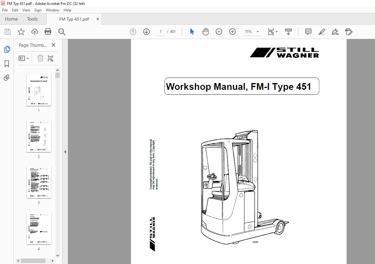
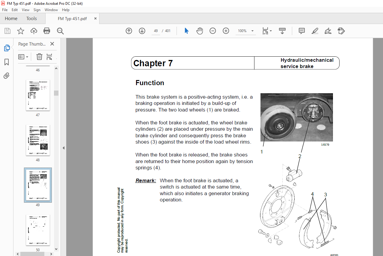
TABLE OF CONTENTS:
Still Wagner FM-I Type 451 Workshop Manual – PDF DOWNLOAD
Chapter 1: Vehicle data
Chapter 2: Drive motor
Chapter 3: Drive wheel
Chapter 4: Gear
Chapter 5: Electro-magnetic parking brake
Chapter 6: Generator service brake
Chapter 7: Hydraulic/mechanical service brake
Chapter 8: Brake deceleration
Chapter 9: Steering
Chapter 10: Guide to the electrical components
Chapter 11: Travel and pump controller (FPS) A10
Chapter 12: Load handling controls module (LAS) 8U61
Chapter 13: Converters 1U6/2U3
Chapter 14: Display 8A5
Chapter 15: CAN bus
Chapter 16: Supply and emergency-stop circuit
Chapter 17: Joystick 2A20
Chapter 18: Single-lever potentiometers 2R9-2R13
Chapter 19: Inductive proximity switches
Chapter 20: Travel transducer 1U20
Issue: Workshop Sheet no
Guide to chapters
Replaces issue: Manual FM-I Type 451 V Copyright protected No part of this manual
may be reproduced in any form Copyright
reserved
05/05
06/03
Chapter 21: DC/DC converter U30
Chapter 22: Height measuring system 8B21
Chapter 23: Seat adjustment
Chapter 24: Hydraulic functions
Chapter 25: Chassis valve block
Chapter 26: Reach carriage valve block
Chapter 27: Additional hydraulics valve block
Chapter 28: Line break protection
Chapter 29: Lowering brake valve
Chapter 30: Load holding valve
Chapter 31: Pump unit
Chapter 32: Pump motor
Chapter 33: Hydraulic pump
Chapter 34: Tank indicator
Chapter 35: Tank
Chapter 36: Runback filter
Chapter 37: Lubrication plan
Chapter 38: Service software
Chapter 39: Error codes
Chapter 40: Winflash
Chapter 41: Height preselection
Guide to components
Issue: Workshop Sheet no
Replaces issue: Manual FM-I Type 451 VI Copyright protected No part of this manual
may be reproduced in any form Copyright
reserved
10/02
• Drive wheel Sheet 3-01
• Brake pedal Sheet 7-05
• DC / DC converter Sheet 21-01 ff
• Display Sheet 14-01 ff
• Speed sensor of drive/hydraulic motors Sheet 13-09
• Speed sensor of drive motor Sheet 02-05
• Speed sensor of hydraulic motor Sheet 32-05
• Pressure relief valve Sheet 25-04
• Single-lever potentiometer Sheet 18-01
• Electro-magnetic parking brake Sheet 5-01 ff
• Travel and pump controller Sheet 11-01 ff
• Travel transducer Sheet 20-01 ff
• Drive motor Sheet 2-01 ff
• Gear Sheet 4-01 ff
• Main brake cylinder Sheet 7-10
• Height measuring system Sheet 22-01 ff
• Hydraulic motor Sheet 32-01 ff
• Hydraulic pump Sheet 33-01
• Hydraulic/mechanical brake Sheet 7-01 ff
• Inductive proximity switch Sheet 19-01
• Actual value potentiometer Sheet 9-15 ff
• Joystick Sheet 17-01 ff
• LAS module Sheet 12-01 ff
• Load holding valve Sheet 30-01
• Line break protection Sheet 28-01
• Steering unit Sheet 9-01 ff
• Steering wheel Sheet 9-14
• Emergency release valve Sheet 25-06
• Proportional valve for lowering Sheet 25-05
• Pump unit Sheet 31-01
• Runback filter Sheet 36-01
• Lowering brake valve Sheet 29-01
• Seat adjustment Sheet 23-01
• Setpoint potentiometer Sheet 9-10 ff
• Tank Sheet 35-01
• Tank indicator Sheet 34-01
• Travel converter Sheet 13-01 ff
• Hydraulic converter Sheet 13-01 ff
• Chassis valve block Sheet 25-01 ff
• Reach carriage valve block Sheet 26-01 ff
• Additional hydraulics valve block Sheet 27-01
02/02
Contents
Issue: Workshop Sheet no
Replaces issue: Manual FM-I Type 451 VII Copyright protected No part of this manual
may be reproduced in any form Copyright
reserved
05/05
• Chapter 1: Vehicle data
-Guide to signs and vehicle number Sheet 1-01
-Production number and consecutive identification numbers Sheet 1-02
-Technical data Sheet 1-03
-Definition of the directions of movement Sheet 1-04
• Chapter 2: Drive motor
-General Sheet 2-01
-Technical data Sheet 2-02
-Connections Sheet 2-02
-Temperature monitoring Sheet 2-03
-Speed sensor Sheet 2-05
-Removal Sheet 2-06
-Installation Sheet 2-09
-Dismantling Sheet 2-10
-Maintenance Sheet 2-12
-Mast hitch Sheet 2-13
-Half mast hitch Sheet 2-14
• Chapter 3: Drive wheel
-Changing the drive wheel Sheet 3-01
• Chapter 4: Gear
-Commissioning Sheet 4-01
-Changing the oil Sheet 4-02
-Removal / installation Sheet 4-03
• Chapter 5: Electro-magnetic parking brake
-General Sheet 5-01
-Function Sheet 5-01
-Removal Sheet 5-02
-Changing the brake disk Sheet 5-03
-Adjusting the brake clearance Sheet 5-04
-Adjusting the braking moment Sheet 5-05
-Releasing the brake mechanically Sheet 5-05
-Checking the brake coil Sheet 5-06
-New magnetic brake from 04/2005 Sheet 5-07
• Chapter 6: Generator service brake
-General Sheet 6-01
-Function Sheet 6-01
10/02
Contents
Issue: Workshop Sheet no
Replaces issue: Manual FM-I Type 451 VIII Copyright protected No part of this manual
may be reproduced in any form Copyright
reserved
02/02
• Chapter 7: Hydraulic/mechanical service brake
-Function Sheet 7-01
-Plan of the braking system Sheet 7-02
-Removal Sheet 7-03
-Adjusting the brake clearance Sheet 7-04
-Adjusting the brake pedal Sheet 7-05
-Bleeding/filling the brake system
• Filling Sheet 7-07
• Bleeding Sheet 7-08
-Main brake cylinder
• General Sheet 7-10
• Special base valve Sheet 7-11
• Removal/installation Sheet 7-12
• Chapter 8: Brake deceleration
-General Sheet 8-01
-Preparations for measurement Sheet 8-01
-Evaluating the measurement
• Testing the service brake Sheet 8-02
• Testing the parking brake Sheet 8-02
• Chapter 9: Steering
-General Sheet 9-01
-Technical data for the steering unit Sheet 9-01
-Function Sheet 9-02
-Block diagram Sheet 9-04
-Steering unit
• General Sheet 9-05
• Connections Sheet 9-05
• Removal Sheet 9-07
• Installation Sheet 9-08
-Removing the drive unit Sheet 9-09
-Setpoint potentiometer
• General Sheet 9-10
• Connections/signals Sheet 9-11
• Testing Sheet 9-12
• Removal Sheet 9-12
• Installation Sheet 9-13
-Adjusting the turning force of the steering wheel Sheet 9-14
-Actual value potentiometer
• General Sheet 9-15
• Connections/signals Sheet 9-16
• Testing Sheet 9-17
• Removal Sheet 9-17
• Installation Sheet 9-18
-Adjusting the entire steering system Sheet 9-19
Issue: Workshop Sheet no
Contents
05/05 Replaces issue: 06/03 Manual FM-I Type 451 Copyright protected No part of this manual
may be reproduced in any form Copyright
reserved
• Chapter 9: Steering
-360° Steering
• General Sheet 9-20
-Recognisable features Sheet 9-21
• Setpoint potentiometer
-General Sheet 9-22
-Connections/signals Sheet 9-23
• Actual value potentiometer
-General Sheet 9-24
-Connections/signals Sheet 9-25
• Steering unit Sheet 9-26
• Drive unit Sheet 9-27
-Software versions Sheet 9-28
• Chapter 10:Guide to the electrical components
-To 04/2005
• Basic equipment Sheet 10-01
• Options Sheet 10-02
• Block diagram Sheet 10-03
-From 05/2005
• Basic equipment Sheet 10-04
• Options Sheet 10-05
• Block diagram Sheet 10-06
More products