$33
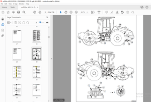
Still Wagner FM Type 447 Workshop Manual 8054226 – PDF DOWNLOAD
Still Wagner FM Type 447 Workshop Manual 8054226 – PDF DOWNLOAD
FILE DETAILS:
Still Wagner FM Type 447 Workshop Manual 8054226 – PDF DOWNLOAD
Language : English
Pages : 329
Downloadable : Yes
File Type : PDF
TABLE OF CONTENTS:
Still Wagner FM Type 447 Workshop Manual 8054226 – PDF DOWNLOAD
A
A/D converter calibration
Actual value potentiometer steering
V8
B18,B27
Additional hydraulics valve blcok
Adjusting of the entire steering system
Adjusting prop valve for lowering
Adjusting prop valve for reach
N18
B22
V21
V22
Adjusting the brake clearance
Adjusting the brake pedal
Adjusting the braking moment
Assemblies
C5,C12
C13
C6
0
B
Bleeding the brake system
Block diagram electrical system
Block diagram hydraulics
C15
M7
N2
Block diagramm steering unit
Brake deceleration
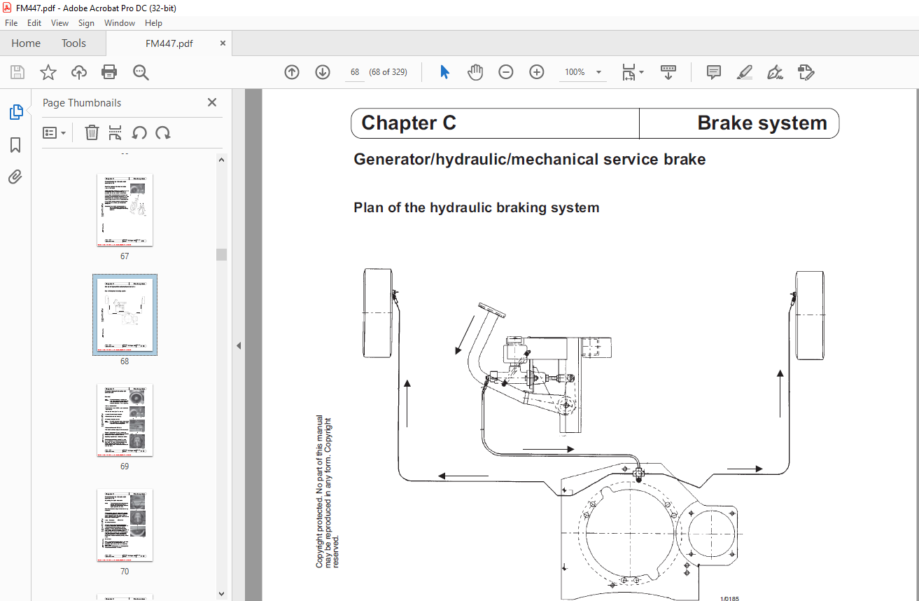
Brake system, general
C
B2
C21
C2
CAN-Bus
Carbon brush monitoring
Changing parameters (LAS)
Changing the brake disk
M93
A4,N26
V18
C4
Changing the configuration
Changing the drive wheel
Changing the gear oil
Changing the hour counter
V49
A9
A17
V59
Changing the parameters in the FPS
Chassis valve block – adjusting work
Checking the brake coil
Commissioning the steering
V47
N10
C7
V5
Commissionning the hydraulics
Components (basic equipment)
Connection FPS START/STOP
Connections FPS
V13
M3
V38
M11
Control of the drive motor
Control of the hydraulics (LAS)
Control signals for DWS reaching
Control signals for DWS tilting
M17
M40
M44
M46
Control signals for hydraulics (FPS)
Control signals for lifting the main lift
Control signals for lowering the main lift
Control signals for LS reaching
M35
M42
M43
M45
Control signals for tilting LS
Control signals for transv reach LEFT with
joystick
Control signals for transv reach RIGHT with
joystick
Control signals for travel
M47
M49
M48
M33
Correcting the staight-on position
D
Data download
Data telegrams
V7
V18
M96
Data Upload
DC/DC converter
Diagnosis connector
Diagnosis standard
V24
M16
M61
V26
Diagnosis, Input Digital LAS
Diagnosis, Setpoint value hydraulics
Diag , Setpoint/actual value sign for steer
Diaphragms
V32
V30
V31
N9, N16
Displays
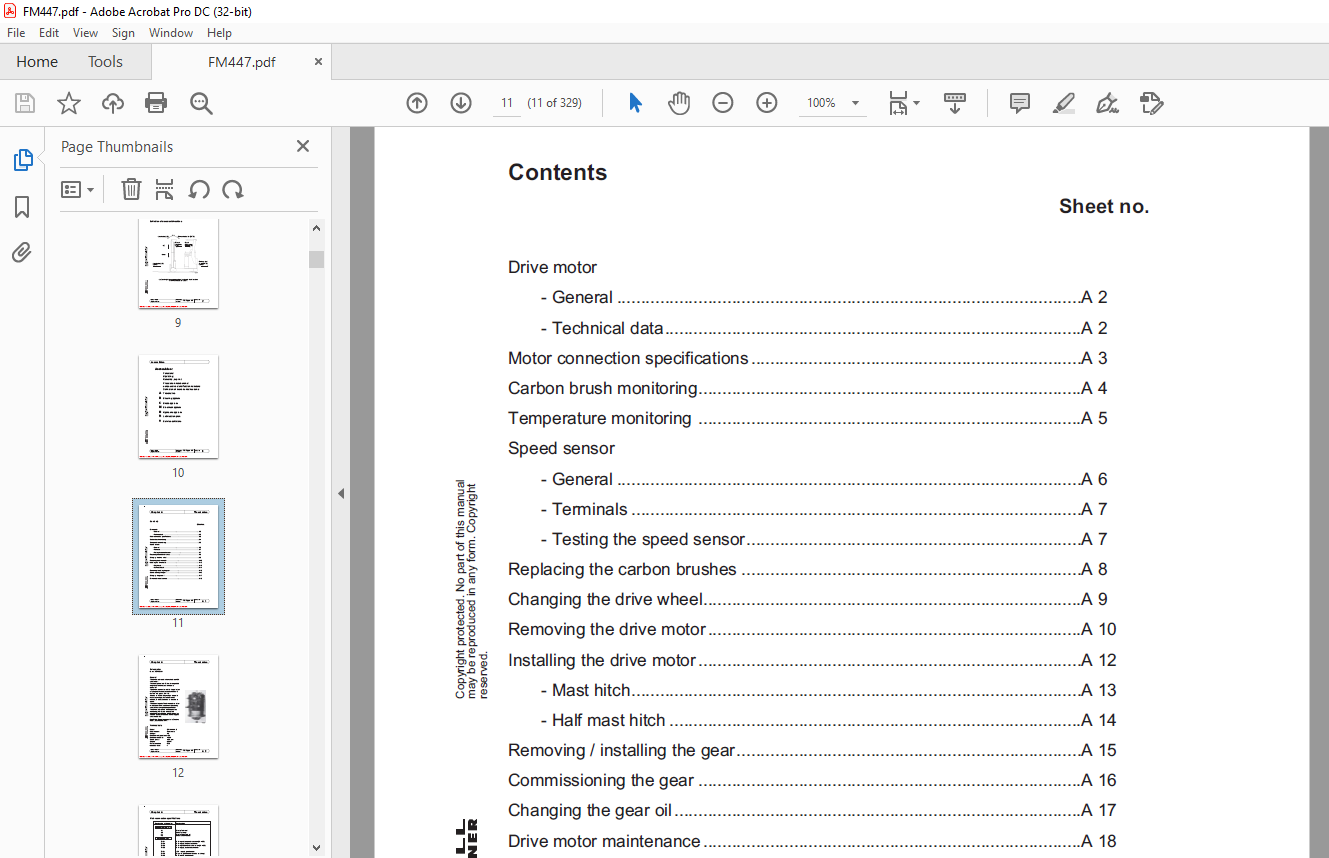
Drive motor conn specifications
Drive motor maintenance
Drive motor, General
M81
A3
A18
A2
Drive motor, Technical data
Drive unit steering unit
E
Electro-magn brake control
A2
B12,B30
M58
Electro-magnetic parking brake
Emergency release valve
Error memory
Errorcode specification
C2
N12
V27,V55
M24,M65
F
Filling the brake system
Flutter
FPS
C15
V10,V93
M8
Function hydr /mech brake
Function Lifting main lift
C9
N3
TRIAL MODE − a valid license will remove this message See the keywords property of this PDF for more information
Index
Copyright protected No part of this manual
may be reproduced in any form Copyright
O
Onboard diagnosis
P
Pin assignment FPS
Pin assignment LAS
M82
M36
M76
Pre-pressure valves for reach
Production number
Pump motor
Pump unit
N19
IV
N25
N23
R
Reach carriage valve block
Reach dampening
Reading data out of the FPS
N14
V39,V46
Reading in the accelerator pedal
Recommended values for initial commissioning
Removal of the loadwheel brake
Removal the steering unit
V51
V20
C11
B10
Removing the drive motor
Removing the gear
Replacing the carbon brushes
Reverse steering
A10
A15
A8,N29
V12,V87
Roll-away monitor
Runback filter
S
Safety circuit FPS
M23
N33
M22
Safety monitoring LAS
Saving the data
Seat adjustment
Sending a data set directly to the FPS
M62
V40
M110
V45
Sensor bearing
Servicemaster, Menu guide
Servicesoftware, general
Setpoint potentiometer steering unit
M108
V4
V2
B13,B25
Signals LAS – FPS
Simultaneous movements
Single-lever potentiometer
Software FPS
M75
M52
M101
M38
Software update LAS V33
Function lowering main lift
Function reach
N4
N5
Function steering unit
Function tilting/transverse shift
G
Gear
B4
N6
A16
General vehicle options
Generator drive motor brake
Guide to wiring FPS
H
M60
C8
M13
Half mast hitch
Height measuring system
Hydraulic options
Hydraulic pump
A14
M105
M55
N31
I
Inductive proximity switches
Installation the steering unit
Installing the drive motor
M102
B11
A12
J
Joystick
L
LAS-Module, General
M99
M39
Line break protection
List of errors
Load file
Load holding valve
N20
V28,V56
V23
N22
Logic board FPS
Lowering brake valve
Lowering speed
Lubrication plan
M14
N21 1
N11
R2
M
Main brake cylinder
Main contactor
Making a connection
C18
M9
V3
Mast hitch
Monitoring electro-magn brake
Movement directions
A13
M59
V
TRIAL MODE − a valid license will remove this message See the keywords property of this PDF for more information
Copyright protected No part of this manual
may be reproduced in any form Copyright
reserved
Index
Issue: 06/03 Workshop Sheet no
Replaces issue: 01/02 Manual FM Type 447 0 3
Software versions display
Software versions LAS
Speed sensor
M92
M80
A6
Steering unit
Steering unit, error codes
T
Tank
B3,B6,B23,B29
B8
N32
Tank display
Teach-In joystick/4-levers
Temperature monitoring
Test function
N32
V14,V84
A5,N27
V52
Travel transducer
Turning force of the steering wheel
V
Valve block chassis, overview
M103
B17
N7
W
WinPulsE, general
Z
Zero point monitoring
V37
M53
IMAGES PREVIEW OF THE MANUAL:
More products