$38
Tadano Carrier ATF-160G5(J)-1 Operation Manual – PDF DOWNLOAD
Tadano Carrier ATF-160G5(J)-1 Operation Manual – PDF DOWNLOAD
FILE DETAILS:
Tadano Carrier ATF-160G5(J)-1 Operation Manual – PDF DOWNLOAD
Language : English
Pages :473
Downloadable : Yes
File Type : PDF
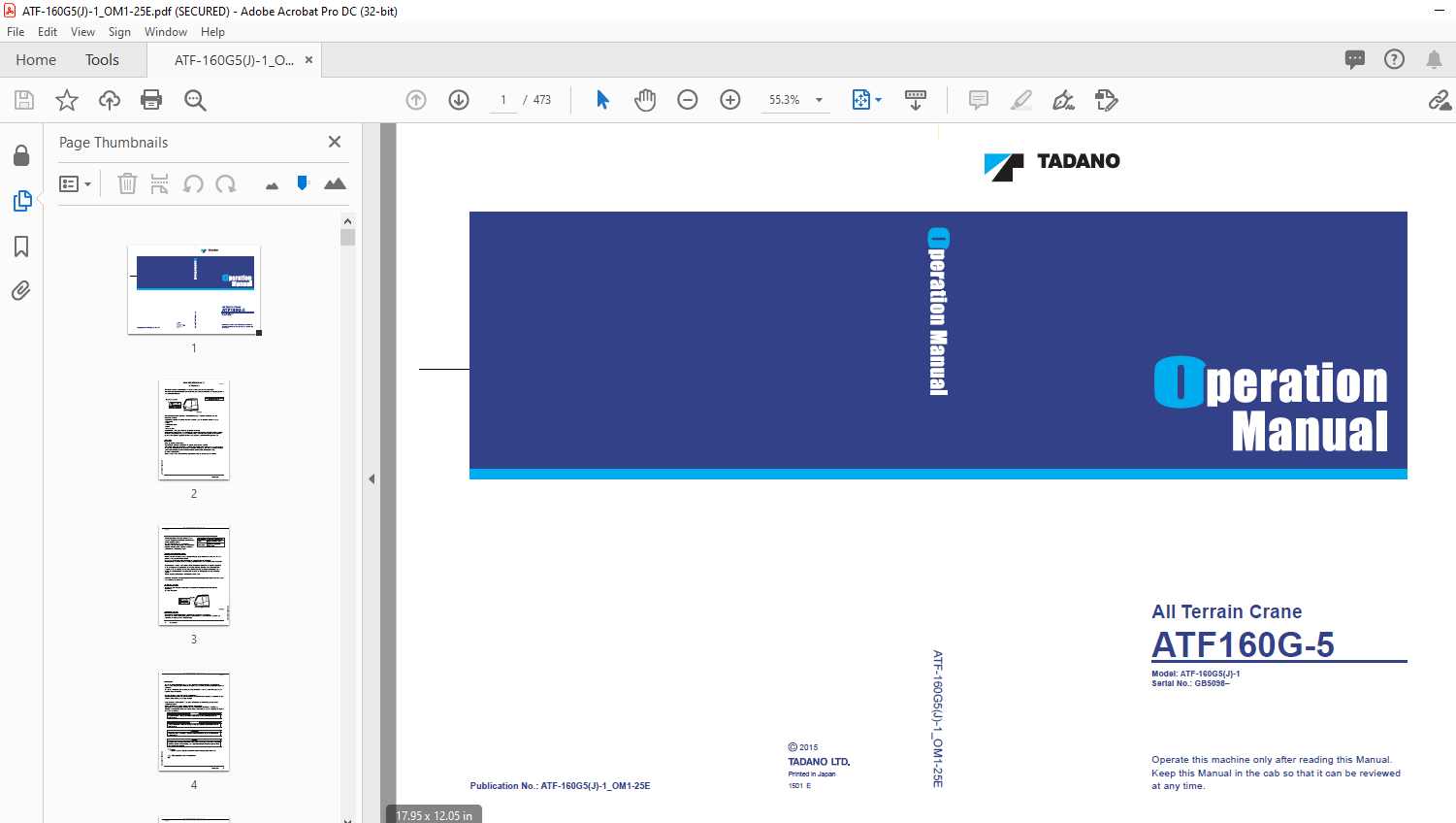
Model: ATF-160G5(J)-1
Serial No.: GB5098–
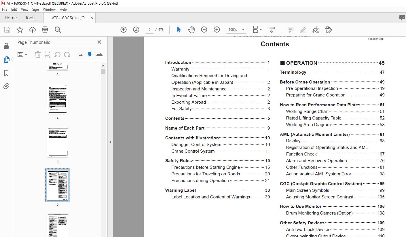
TABLE OF CONTENTS:
Tadano Carrier ATF-160G5(J)-1 Operation Manual – PDF DOWNLOAD
Introduction 1
Warranty 1
Qualifications Required for Driving and
Operation (Applicable in Japan) 2
Inspection and Maintenance 2
In Event of Failure 2
Exporting Abroad 2
For Safety 3
Contents 5
Name of Each Part 9
Contents with Illustration 10
Outrigger Control System 10
Crane Control System11
Safety Rules 15
Precautions before Starting Engine 15
Precautions for Traveling on Roads 20
Precautions during Operation 21
Warning Label 38
Label Location and Content of Warnings 39
OPERATION45
Terminology 47
Before Crane Operation 49
Pre-operational Inspection 49
Preparing for Crane Operation 49
How to Read Performance Data Plates 51
Working Range Chart 51
Rated Lifting Capacity Table 52
Working Area Diagram 58
AML (Automatic Moment Limiter) 61
Display 63
Registration of Operating Status and AML
Function Check 67
Alarm and Recovery Operation 76
Other Functions 81
Action against AML System Error 98
CGC (Cockpit Graphic Control System) 99
Main Screen Symbols 99
Adjusting Monitor Screen Contrast 105
How to Use Monitor 106
Drum Monitoring Camera (Option) 108
Other Safety Devices 109
Anti-two-block Device 109
Over-unwinding Cutout Device110
Anemometer111
AML External Indicator Lamp (Option)112
Outriggers113
Outrigger Control Panel114
Outline of Outrigger Extending Operation118
Outrigger Set-up 120
Extending Outriggers 121
Horizontal Set-up 125
Outline of Outrigger Stowing Operation 127
Retracting Outriggers 128
Outrigger Operation While Traveling in
Work Site131
Entering Cab 133
Opening/Closing Door 133
Opening/Closing Windshield 134
Adjusting Seat Tilt 135
Adjusting Seat 136
Adjusting Control Lever Stand 139
Sun Visor 139
Starting and Stopping Engine 14 0
How to Start Engine 143
How to Start Engine in Cold Season 144
How to Stop Engine 145
Functions of Control Lever and Pedal 14 7
Hoisting 15 0
Hoisting Up/Down Operation 152
Winch Speed Changeover Operation 155
Drum Rotation Indicator 156
Lift Adjuster Operation 157
Boom Telescoping Operation 160
Outline of Telescoping System 163
Types of Telescope Mode 164
Normal Telescoping Operation 165
Maintenance Telescoping174
Slow Telescope Mode 180
Boom Telescoping Speed Changeover
Operation 182
Elevating Boom 184
Elevating Boom 186
Slow Stop Cancel Switch 188
Changing Boom Elevating Speed 189
Slewing Operation 190
Slewing Operation 191
Slow Stop Cancel Switch 193
Slewing Lock Operation 194
Slewing Alarm Switch (Option) 195
Full Automatic Luffing Jib (FLJ) Operation 196
Full Automatic Luffing Jib Operation 199
Changing Jib Speed 203
Reeving Wire Ropes 204
Standard Number of Parts of Line 204
Reeving Procedure 210
Single Top 21 3
Mounting Single Top 214
Stowing Single Top 218
Accessories in Cab 22 1
Heater and Air Conditioner 222
How to Use Other Accessories 225
MOUNTING/DISMOUNTING22 9
Mounting/Dismounting Boom and Elevating
Cylinder 23 1
Mounting Boom and Elevating Cylinder 232
Dismounting Boom and Elevating Cylinder 253
Mounting/Dismounting Counterweight 273
Combinations of Counterweights 273
Mounting Counterweight 278
Dismounting Counterweight 286
Mounting/Dismounting Full Automatic
Luffing Jib (FLJ) 293
Mounting Full Automatic Luffing Jib (FLJ) 294
Dismounting Full Automatic Luffing Jib (FLJ)311
Stowing Hydraulic Hose When Jib is Not Used
(For Serial No GB5104 or Later) 327
INSPECTION AND MAINTENANCE32 9
Precautions for Inspection and Maintenance 33 1
Precautions for Inspection and Maintenance 331
Inspection and Maintenance 33 9
About Inspection and Maintenance 339
Legal Inspection 339
Periodic Replacement Part 340
Inspection and Maintenance Interval 341
Pre-operational Inspection 34 6
Engine 347
Hydraulic System 352
Control System 354
Outrigger System 355
Slewing System 357
Boom, Jib System 357
Lifting Device 359
Safety Devices 362
Inspection of Crane Structure 365
Greasing 367
Maintenance Table 368
Greasing Chart 369
Greasing Centralized Lubrication Device374
Gear Oil 375
Maintenance Table 375
Winch Speed Reducer
(Main/Auxiliary Winch) 376
Winch Motor Coupling 377
Slewing Speed Reducer 378
Engine 380
Maintenance Table 380
Engine Oil 381
Air Cleaner 383
Engine Cooling System 385
Maintenance Table 385
Coolant 386
Radiator 386
Fuel System 387
Maintenance Table 387
Fuel tank 388
Water Separator 388
■ Hydraulic System 391
Maintenance Table 392
Hydraulic Oil Tank 393
Line Filter 396
Slewing System 397
Maintenance Table 397
Slewing Bearing Mounting Bolt 397
Outrigger System 399
Maintenance Table 399
Chain for Telescoping 399
Electrical System 402
Maintenance Table 402
Fuse Replacement 402
Battery Electrolyte Inspection 403
Wire Rope 405
Replacing Wire Ropes 405
Handling Wire Ropes414
Action against Emergency41 7
If Boom Cannot be Telescoped417
Action against Abnormality (A) 422
Action against Abnormality (B) 430
Action against Abnormality (C) 437
If Error Occurs in AML System 438
If Error Occurs with AML Main Body 439
If Crane Operation Does Not Stop Even When
Control Lever is Returned to Neutral Position 440
If Weight Set Failure Warning Lamp Does Not
Go Out 441
If Engine Cannot be Started/Stopped 442
If Battery Is Exhausted 443
INFORMATION AND DATA44 5
Conversion Tables 44 7
The Safety Ordinance for Cranes (Japan) 44 8
Hand Signals 45 7
Major Specifications 45 8
Crane 458
Overall Dimensions 459
Relief Valve Set Pressure 460
Wire Rope Specifications 460
Hook Block Mass 460
Others 460
Oils and Greases 461
Oils and Greases Table 461
Recommended Oils and Greases 462
Main Transportation Component List 464
Mass Distribution List 466
IMAGES PREVIEW OF THE MANUAL:
More products