$45
Terex Crane AC 300 Operator & Maintenance Manual – PDF DOWNLOAD
Terex Crane AC 300 Operator & Maintenance Manual – PDF DOWNLOAD
FILE DETAILS:
Terex Crane AC 300 Operator & Maintenance Manual – PDF DOWNLOAD
Language : English
Pages : 1834
Downloadable : Yes
File Type : PDF
IMAGES PREVIEW OF THE MANUAL:
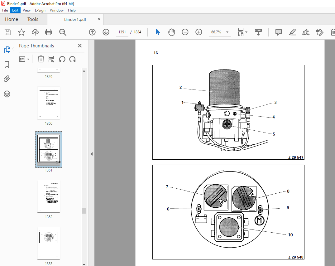
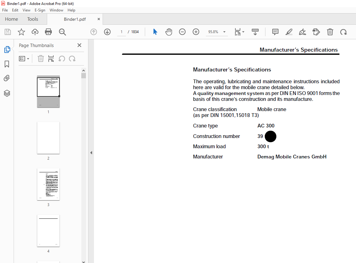
TABLE OF CONTENTS:
Terex Crane AC 300 Operator & Maintenance Manual – PDF DOWNLOAD
Manufacturer’s Specifications 1
Foreword 1
1 Safety Instructions 1
1 1 General 1
1 2 Intended Use 3
1 3 Operating Conditions and Computed Design of the Crane 5
1 3 1 General 5
1 3 2 Classification of the Crane 5
1 3 3 Classification of the Engines 7
1 3 4 Workplace Ergonomics 9
1 3 5 Load and Utilisation of the Crane 9
1 3 6 Required Ambient Conditions 11
1 3 7 Service Life 13
1 3 8 Standards and Calculation Regulations 15
1 3 9 Dangers to Air Traffic 17
1 4 Safety Regulations 19
1 4 1 Organisational Measures 21
1 4 2 Selection and Qualifications of Personnel 23
1 4 3 Particular Hazards 25
1 4 4 Combination of Hazards with Combined Operation
of Two or More Cranes 35
1 4 5 Driving Operation 39
1 4 6 Crane Operation 43
1 4 7 Power Supply Failure 61
1 4 8 When Assembling and Dismantling Crane Components 63
1 5 Hand Signals 69
1 5 1 General Hand Signals 71
1 5 2 Hand Signals for Working Movements 73
1 5 3 Hand Signals for Driving Movements 75
2 Structure of the Mobile Crane 3
2 1 Dimensions 3
2 2 General view 5
2 3 Superstructure 7
2 4 Safety Components 9
2 4 1 Ladders and Catwalks 9
2 4 2 Emergency Exit 9
2 5 Signs 11
2 5 1 Signs in the crane operator’ s cab 11
2 5 2 Signs on the Superstructure 15
2 5 3 Safety Signs 17
Index
300–1003–118 2
4 Crane Operator’s Cab 3
4 1 Controls and Displays 3
4 2 Instrument Panel 7
4 3 Entering the Cab 21
4 4 Tilting the Cab 23
4 5 Adjusting the Crane Operator’s Seat 25
5 Engine 3
5 1 Before Starting the Engine 3
5 2 Starting 5
5 2 1 Starting Procedure 7
5 2 2 Starting Difficulties 9
5 2 3 After Starting the Engine 11
5 2 4 Jump Starting 13
5 2 5 Warming Up the Hydraulic System 15
5 3 Switching Off the Engine 19
5 4 Engine–Independent Heater with Radiator Pre–Heater 21
5 4 1 General 21
5 4 2 Operational elements 23
5 4 3 Setting 25
5 4 4 Heater operation without preselection 27
5 4 5 Heating operation with preselection 31
5 4 6 Display of temperature 35
5 4 7 Elimination of malfunctions 35
8 Slewing the Superstructure 3
8 1 Slewing and Braking the Superstructure 5
8 2 Precision Control of the Slew Gear
(Adjustment of Desired Value) 11
Index
300–1003–118 3
9 Counterweight 3
9 1 General 3
9 2 Load Capacity Tables for Fitting and Removing the
Counterweight Elements 5
9 3 Counterweight Combination 0 t 13
9 4 Counterweight Combination 11 t 13
9 4 1 Fitting the 11 t Counterweight Combination 13
9 4 2 Removing the 11 t Counterweight Combination 43
9 5 Counterweight Combination 22 t 47
9 5 1 Fitting the 22 t Counterweight Combination 49
9 5 2 Removing the 22 t Counterweight Combination 49
9 6 Counterweight Combination 33 t 51
9 6 1 Fitting the 33 t Counterweight Combination 53
9 6 2 Removing the 33 t Counterweight Combination 53
9 7 Counterweight Combination 44 t 55
9 7 1 Fitting the 44 t Counterweight Combination 57
9 7 2 Removing the 44 t Counterweight Combination 57
9 8 Counterweight Combination 55 t 59
9 8 1 Fitting the 55 t Counterweight Combination 61
9 8 2 Removing the 55 t Counterweight Combination 61
9 9 Counterweight Combination 76 t 63
9 9 1 Fitting the 76 t Counterweight Combination 65
9 9 2 Removing the 76 t Counterweight Combination 65
9 10 Counterweight Combination 100 t 67
9 10 1 Fitting the 100 t Counterweight Combination 69
9 10 2 Removing the 100 t Counterweight Combination 69
Index
300–1003–118 4
10 Safety Equipment 3
10 1 Electronic Crane Information System (ECIS) 3
10 1 1 System Start 9
10 1 2 Operating and Display Elements 11
10 1 3 LCD Display 13
10 1 4 Function Display ”K” 17
10 1 5 Setting the Operating Mode 23
10 1 6 Tilt Display 45
10 1 7 Load Monitoring Assembly 47
10 1 8 Relative Working Radius 49
10 1 9 Setting the Parameters 53
10 1 10 Error Diagnosis System of the PDC System 79
10 1 11 Error Diagnosis System of the Inputs and Outputs 85
10 2 Bridging the Load Limit Device 101
10 2 1 Bridging Shut–Down of Load Moment Reducing Movements 101
10 2 2 Bridging the Shut Down of all Movements 103
10 3 Limit Switches 105
10 3 1 Bridging the Hoist Limit Switch 105
10 3 2 Bridging the Lower Limit Switch 105
10 3 3 Limit Switch ”High/Low Position — Luffing Fly Jib” 105
10 4 Support Forces 107
10 4 1 Monitoring and Displaying the Support Forces 107
10 4 2 Setting the Support Force Limit Values 109
10 4 3 Calculating the Support Forces 111
10 5 Electrical Safety Chain 113
10 5 1 Main Boom Operation 113
11 Working Instructions 3
11 1 Wind Speeds 3
11 1 1 Permissible Wind Speeds for Erection 5
11 1 2 Permissible Wind Speeds for Crane Operation 5
11 1 3 Impermissible Wind Speeds 7
11 2 Crane Operation 11
11 3 Operation Planning / Monitoring Safety Measures 19
11 3 1 General 19
11 3 2 Condition of the Crane 19
11 3 3 Condition of the Environment 21
Index
300–1003–118 5
12 Telescoping 3
12 1 General 3
12 2 Locking and Bolting Unit 5
12 3 Controls 9
12 4 Telescoping Information System 15
12 4 1 General 15
12 4 2 Operating Principle 17
12 4 3 Loss of Signal from the Length Sensors 19
12 5 Extension Lengths of the Telescopic Sections 23
12 5 1 Standard extension lengths 23
12 5 2 Special extension lengths 25
12 5 3 Monitoring the Extension Lengths while Telescoping 27
12 5 4 Extension Sequence of the Telescopic Sections 27
12 6 Telescoping Procedure 29
12 6 1 General 29
12 6 2 Telescoping Example 31
12 7 Telescopic Loads 49
13 Luffing 3
14 Hoist 1 3
15 Hoist 2 (Optional) 3
15 1 Fitting and Removing Hoist 2 or Replacement Weight 3
15 2 Hook Operation with Hoist 2 5
15 3 Luffing the Fly Jib using Hoist 2 (with Optional
Equipment Luffing Fly Jib) 11
16 Heating and Ventilation 3
16 1 Engine–Driven and Non–Engine–Driven Heaters 3
16 2 Air Conditioning Equipment (Optional) 5
Index
300–1003–118 6
17 Reeving 3
17 1 General 3
17 2 Load Lifting Equipment 5
17 2 1 Hoist ropes 7
17 2 2 Hook Blocks 13
17 3 Reeving the Hoist Rope on the Main Boom Head 19
17 3 1 HD Attachment (Option) 19
17 3 2 Reeving 2 x 14–Fold (Optional) 25
17 3 3 Reeving 23–, 21–fold 31
17 3 4 Reeving 20–, 19–fold 33
17 3 5 Reeving 18–, –17, –16–fold 35
17 3 6 Reeving 15–, 14–, 13–, 12–fold 37
17 3 7 Reeving 11–, 10–, 9–, 8–fold 39
17 3 8 Reeving 7–, 6–, 5–, 4–fold 41
17 3 9 Reeving 3–, 2–, 1–fold 43
17 4 Reeving the Hoist Rope on the Head of
the Main Boom Extension 45
17 4 1 Guiding the rope to the Head of the Main Boom Extension 45
17 4 2 Reeving the Hook Block 45
17 5 Reeving the Hoist Rope on the Head of the Luffing Fly Jib 47
17 5 1 Guiding the Rope to the Head of the Luffing Fly Jib 47
17 5 2 Reeving the Hook Block 51
17 6 Reeving the Hoist Rope on the Head of the Fixed Fly Jib 59
17 6 1 Guiding the Rope to the Head of the Fixed Fly Jib 59
17 6 2 Reeving the Hook Block 63
17 7 Reeving the Hoist Rope on the Head Sheave 65
17 7 1 Guiding the Rope to the Head Sheave 65
17 7 2 Reeving the Hook Suspension Gear 65
17 8 Auxiliary Reeving Winch (Optional) 67
17 8 1 Reeving the Hook Block on the Main Boom Head 67
17 8 2 Reeving the Luffing Rope 71
Index
300–1003–118 7
18 Main Boom Extension 1
18 1 General 1
18 2 Components 3
18 3 Fitting and Removing Using an Auxiliary Crane 5
18 3 1 Before Fitting 5
18 3 2 Fitting 7
18 3 3 Removal 15
18 4 Folding Procedure 19
18 4 1 Before Folding 19
18 4 2 Folding out of Transport Position into Operating Position 21
18 4 3 Folding from Operating Position into Transport Position 43
18 4 4 Operating the Main Boom with the Main Boom
Extension Folded Alongside 55
18 5 Setting the Operating Angle 59
18 5 1 Adjusting from 0 to 20 Degrees Position 59
18 5 2 Adjusting from 20 to 0 Degrees Position 63
18 6 Telescoping the Main Boom with the Main Boom
Extension Attached 65
18 6 1 Telescoping Procedure 65
18 7 Main Boom Extension with Superlift 67
18 8 Notes on Transport 67
18 9 Main Boom Extension with Intermediate Section
(21 7 m), optional 71
18 9 1 General 71
18 9 2 Components 71
18 9 3 Fitting and Removal 71
18 9 4 Folding Procedure 89
18 9 5 Adjusting the Operating Angle 89
18 9 6 Telescoping the Main Boom with
the Main Boom Extension Fitted 89
18 9 7 Main Boom Extension with Superlift 89
18 9 8 Notes on Transport 89
Index
300–1003–118 8
19 Luffing Fly Jib 1
19 1 General 1
19 2 Components 3
19 3 Possible Combinations 5
19 4 Transport Proposal 9
19 4 1 Transport Unit 1 9
19 4 2 Transport Positions for Transport Unit 1 11
19 4 3 Transport Unit 2 13
19 4 4 Transport Positions for Transport Unit 2 15
19 5 Before Mounting 17
19 6 Mounting 23
19 6 1 Mounting without assist crane 25
19 6 2 Mounting using an assist crane 59
19 7 Before Erection 71
19 8 Erection 77
19 8 1 General Description 79
19 8 2 Example of how to Achieve Erection Configuration 83
19 9 Erection 85
19 10 Operating with the Luffing Fly Jib 103
19 11 Lowering 105
19 12 Dismounting 123
19 12 1 Dismounting without assist crane 125
19 12 2 Dismounting using an assist crane 127
20 Fixed Fly Jib 1
20 1 General 1
20 2 Components 3
20 3 Possible combinations 5
20 4 Transport Proposal 7
20 5 Before Mounting 7
20 6 Mounting 11
20 6 1 Mounting without assist crane 13
20 6 2 Mounting using an assist crane 35
20 7 Raising 47
20 8 Lowering 49
20 9 Dismounting 51
20 9 1 Dismounting without assist crane 51
20 9 2 Dismounting using an assist crane 53
20 10 Superlift Operation with Fixed Fly Jib 59
Index
300–1003–118 9
27 Luffing Fly Jib with Superlift 3
27 1 General 3
27 2 Components 3
27 3 Combination Options 3
27 4 Transport Suggestion 3
27 5 Before Fitting the Luffing Fly Jib 5
27 6 Fitting the Luffing Fly Jib 9
27 7 Before Erecting 15
27 8 Configuring 15
27 8 1 General Description 17
27 8 2 Configuration Example 23
27 9 Erecting 27
27 10 Operation 37
27 10 1 General 37
27 10 2 Telescoping to a Different Setting 41
27 11 Lowering the Luffing Fly Jib 57
27 12 Removal 57
30 Superlift 1
30 1 General 1
30 2 Components 3
30 3 Transport Proposal 5
30 4 Before Fitting 7
30 5 Attachment 9
30 6 Erecting the Bracing Support 37
30 6 1 Before Erecting the Bracing Support 37
30 6 2 Erection Procedure 39
30 7 Superlift Operation 45
30 7 1 Operating Instructions 45
30 7 2 Telescoping the Main Boom with Superlift 47
30 7 3 Checking the Main Boom Bracing 59
30 7 4 Superlift Operation with Additional Equipment 63
30 8 Lowering the Bracing Support 67
30 9 Removing the Superlift 79
30 10 Superlift Remaining on the Main Boom 85
More products