$28
Terex Crane RT300 / RT500 (82.5878.3, 82.5879.3) Service Manual – PDF DOWNLOAD
Terex Crane RT300 / RT500 (82.5878.3, 82.5879.3) Service Manual – PDF DOWNLOAD
FILE DETAILS:
Terex Crane RT300 / RT500 (82.5878.3, 82.5879.3) Service Manual – PDF DOWNLOAD
Language : English
Pages : 83
Downloadable : Yes
File Type : PDF
IMAGES PREVIEW OF THE MANUAL:
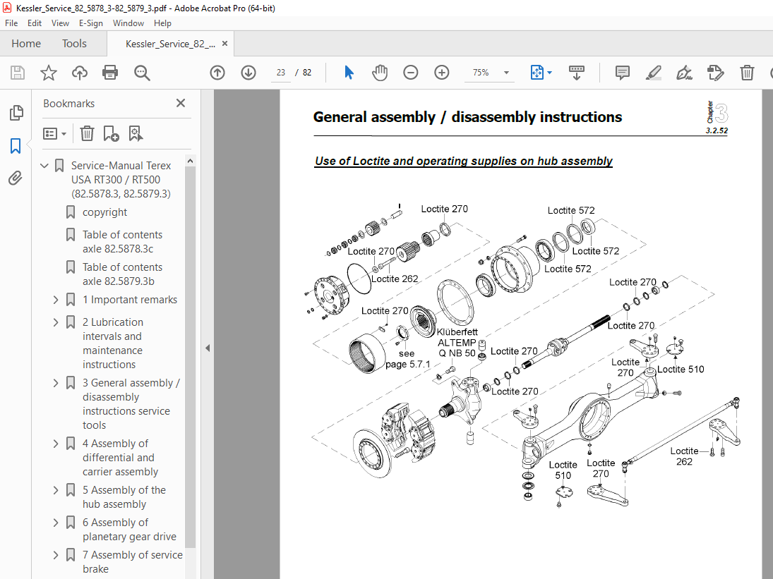
TABLE OF CONTENTS:
Terex Crane RT300 / RT500 (82.5878.3, 82.5879.3) Service Manual – PDF DOWNLOAD
Service-Manual Terex USA RT300 / RT500 (82 5878 3, 82 5879 3) 1
copyright 3
Table of contents axle 82 5878 3c 4
Table of contents axle 82 5879 3b 5
1 Important remarks 6
1 1 Important remarks 7
1 1 Checking of screw connections, safety devices and corrosion 7
1 1 Check of brakes 7
1 1 Service instructions 8
1 3 Instructions for ordering spare parts 9
1 3 Warranty 9
1 3 Ordering 9
1 3 Identification plate 9
1 3 Necessary to contact Kessler & Co GmbH & Co KG 10
2 Lubrication intervals and maintenance instructions 11
2 1 General lubrication instructions 12
2 1 Fill levels 12
2 1 Preservation of Kessler axles for an extended storage period 12
2 1 Before putting the axle into operation 12
2 2 Lubrication points axle 82 5878 3 13
2 2 Lubrication points axle 82 5879 3 14
2 3 Lubricants and lubrication intervals 15
2 3 Important – if a noise is produced on axles with self locking differentials 16
2 3 1 Recommendable hypoid gear oils corresponding MIL-L 2105 B/API GL 5 resp MIL-L 2105 C/D/API GL 5 17
2 4 General maintenance instructions 18
3 General assembly / disassembly instructions service tools 19
3 1 General instructions for correct assembly and disassembly 20
3 1 General instructions for disassembly 20
3 1 General instructions for assembly 20
3 2 1 Application of Loctite and operating supplies 21
3 2 1 Application of Loctite and operating supplies 21
3 2 1 Remarks for working up Loctite and operating supplies 21
3 2 52 Loctite on hub assembly 22
Use of Loctite and operating supplies on hub assembly 22
Use of Loctite and operating supplies on hub assembly 23
3 2 19 Use of Loctite and operating supplies of wheel drive assembly 24
3 3 Tightening torques 25
3 3 General instructions for tightening torques (Nm) 25
3 3 Tightening torque of metric coarse-pitch thread 25
3 3 Tightening torque of metric fine pitch thread 26
3 3 Thigtening torque for galvanized bolts and nuts! 26
3 3 Tightening torque for brake caliper dowel screws (greased !) 26
3 3 Tightening torque of the nut for steering stop 26
3 3 Approximate value for the thigthening torque for screw plug 26
3 3 1 Units 27
3 3 1 Comparison table for units 27
3 3 1 Names of the legal units 27
3 4 1 Tightening torques of wheel nut with thrust collar 28
3 4 Wheel nut with thrust collar 28
3 4 Wheel nut with clamp (for clamp fixation) 28
3 4 Wheel nut with spring lock 28
3 5 Tightening torques for castle nuts and adjusting nuts 29
3 5 Tightening torques for castle nuts on ball joints for track rods and ram cylinders 29
3 5 Tightening torque of the adjusting nut resp slotted nut at flanges resp gearwheels ect 30
3 6 36 Tools of the drive assembly 31
3 6 85 Tools of the hub assembly 32
4 Assembly of differential and carrier assembly 35
4 0 1 Contact pattern of bevel gear teeth 36
4 0 1 Adjustment of contact pattern of bevel gear teeth 36
Checking the contact pattern of the gear teeth 37
4 0 2 striking nut 38
4 0 2 Securing of the striking nut 38
4 0 2 Use of Loctite and other operating supplies 38
4 0 2 Removing of the striking nut 39
4 1 Differential and carrier assembly A51 40
4 1 1-51 drive pinion distance 41
4 1 1-51 Adjustment of drive pinion distance 41
4 1 1-51 Sample calculations (dimensions in mm) 42
4 1 2 Assembly of drive pinion bearing 43
4 1 3 Assembly of the Differential 44
4 1 4-51 Backlash 45
4 1 4-51 Dimension of backlash 45
4 1 4-51 Adjustment of backlash 46
5 Assembly of the hub assembly 47
5 1 Hub assembly steer drive axle 48
5 1 1 Assembly bearing of steering knuckle and bearing of universal joint 49
5 1 2 Assembly of the differential and carrier assembly onto the axle housing 50
5 1 3 Assembly of the steering knuckle onto the axle housing 51
5 1 4 Assembly of steering- resp track rod lever 52
5 1 5 1 Assembly of the hub assembly 53
5 1 6 Assembly of the spacer ring 54
5 5 6 Prepare and mount wheel hub 55
5 7 1 Adjusting of wheel bearings 56
5 7 1 Wheel safety nut 56
6 Assembly of planetary gear drive 57
6 5 Planetary gear drive 58
6 5 1 Assembly of ring gear and ring gear carrier/ Assembly of sun gear 59
6 1 2 Assembly of planetary gear 60
6 5 2 Adjustment of axial clearance/ Assembly of planetary housing 61
6 1 4 Disassembly of planetary gear 62
7 Assembly of service brake 63
7 0 1 Instruction for the servicing and repair of hydraulic and mechanically actuated drum and disc brakes 64
Instruction for the servicing and repair of fixed caliper hydraulic disc brakes TM70/98 65
1) Description of the function (version including cylinderinsets) 65
2) Maintenance / Servicing and Repair 65
2a) Brake pad renewal 65
2b) Seal renewal 66
2c) Remarks 67
3) Description of the eletctric wear indicator 67
General 67
Function 67
Maintenance and repair 67
4) Description of mechanical wear indicator (sliding-block version) 68
General 68
Function 68
Maintenance and repair 68
7 3 7 Brake disc 69
8 Assembly of parking brake 70
8 0 1 Spring – loaded sliding caliper brakes 71
TM6397 pdf 0
1 Constructions and funktion 72
2 Mounting and basic setting regulations 73
2 1 Mounting the brake 73
2 2 Basic setting regulation 74
2 3 Adjusting regulations 74
3 Emergency release of the praking brake 75
4 Maintance and repair work 76
4 1 Maintenance and exchange of brake pads 76
4 2 Changing the seal 78
4 3 General 79
7 3 7 Brake disc 80
Kessler & Co GmbH & Co KG 82
More products