$39
Terex Crawler Crane HC 185 Operation Manual – PDF DOWNLOAD
Terex Crawler Crane HC 185 Operation Manual – PDF DOWNLOAD
FILE DETAILS:
Terex Crawler Crane HC 185 Operation Manual – PDF DOWNLOAD
Language : English
Pages : 466
Downloadable : Yes
File Type : PDF
IMAGES PREVIEW OF THE MANUAL:
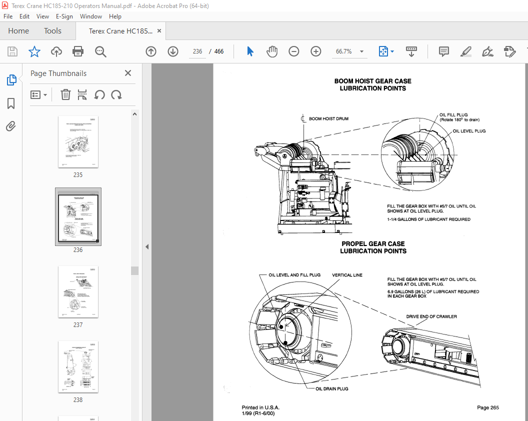
TABLE OF CONTENTS:
Terex Crawler Crane HC 185 Operation Manual – PDF DOWNLOAD
SUBJECT PAGE NO
American Crane Warnings
Preface 1
1 MACHINERY PLAN AND ELEVA TION
Crawler Crane О
Crawler Crane with W0RKH0RSE 0 1
Crawler Crane with W0RKH0RSE 0 2
General Dimensions 1
Machinery Plan View 2
Right Hand Elevation View 3
Left Hand Elevation View 4
Crawler Lower 5
Performance Specifications 6
General Specifications 8
2 OPERATION
Operation Guidelines 101
lmportant Cautions & Warnings 103
Accident Prevention Signs 105-106
Danger Zone Near Electrical Transmission Lines 107
Audio & Visual Warning Systems for Safety 108
Operating lnstructions Warning 109
Control Summary – Layout 11 О
Operator’s Control Console lndex 111
Pre Operation lnspection 112
Starting Operation 113-116
Fueling Operation 116 1
Auto Lube Operation 117-118
Swinging Operation 119-121
Traveling Operation 122-123
Hoist Operation 124-126 2
Operation in Duty Cycle Mode 127
Operation in Crane Mode 128
Operation in Erect Mode 129
Operation in Clam Mode 130
Front and Rear Drum Dog Operation 131
Third Drum Operation 132
Boom Hoist Operation 133-135
Auxiliary Functions 136
Wylie Load Moment lndicator (LMI) Operation 137-145
Anti-Two Block Override 145 1
W0RKH0RSE Attachment Operation 146-150 (НС 185) 146-148 (НС 21 О)
РАТ Load Moment lndicator (LMI) Operation 151 01-151 37
Operator’s Seat 153
Avoiding Rotation of Suspended Loads 155
Working with the W0RKH0RSE Counterweight Fully Extended (НС 185 ONL У) 160-162
Operating Cranes in Extreme Cold 165-165 4
Hand Signals 170-171
Recommended Storage Precautions 187
Printed in U S A Page 1
1/99 (R11-1/02)
TABLE OF CONTENTS
НС 185/НС 21 О
3 LUBRICA TION
General Lubrication lnformation 201
Crane Upper and Lower Lubrication 221
Lubrication lnterval Chart 251
Lubrication, Fuel and Coolant Specifications 252
Location of Auto Lube Components 255
Auto Lube System Diagram 256
Auto Lube Stem Function Description 257
Auto Lube System Check – Visual Check Procedure 258-261 1
Lubrication Points
Swing System Lubrication 262
Swing Planetary Lubrication 263
Front & Rear Drum Shaft & Pillow Block Bearings 264
Boom Hoist Gear Case 265
Visual Check Procedure – Third Drum 266
Hammerhead Boom Tip 267
Offset Tip 268
Recommended Lubricants 271-27 4
4 HVDRAULIC SVSTEMS
Hydraulic Component Locations 400-401
Hydraulic Component List 402-404
Hydraulic Specifications 41 О
Hydraulic System Summary 411
Hydraulic System Description 412-414
lnspection, Maintenance and TrouЫeshooting 415-420
Contaminant Test Procedure for Hydraulic Fluid 421 00-421 11
Hydraulic Schematics 425-432
5 ELECTRICAL SVSTEMS
Schematic Sheets (НС 185 ONL У) 530-539
Schematic Sheets (Without WORKHORSE) (НС 185 ONL У) 540-547
Schematic Sheets (НС 210 ONL~ 550-558
6 ВООМ RIGGING AND JIB
Boom Composition 600
lmportant Notes Concerning Rigging 601
General Boom lnstallation lnformation 601 01 -603 01
Boom Stops Shipping Position 603 8
Boom lnner lnstallation Procedure 604 00-604 01
Boom lnner Removal Procedure 605 00-605 01
Load Out Procedure 605 02
Boom AssemЫy with Assist Crane 606 00-607 01
Boom AssemЫy without Assist Crane 608 00-612 01
Wind Speed Limitations 615
Raising and Lowering Long Booms 616-617
Typical Blocking of Track Side Frames for Long Boom Erection or Lowering 618
Wire Rope Specifications & Drum Capacity 619
Printed in U S A
1/99 (R11-1/02)
Page2
Т ABLE OF CONTENTS
НС 185/НС 210
6 ВООМ RIGGING AND JIB (Continued)
lnstalling Wire Rope Onto а Drum 620
Pulling the Load Line from the Boom Tip to the Drum 621-622
Attaching the Ropes to the Drums 623
Pulling the Load Line from the Drum to Boom Tip 624-625
Wire Rope Clip lnstallation Procedure 626-627
Securing the Dead End of а Rope When Using а Wedge Socket 628
Wedge Socket Warning & Application lnstructions 630
Reeving Diagrams
77″ SH Boom with Luffing Tip – 1, 2, 3, 4, 5, 6, 7 & 8 Parts of Line 635-635 3
77″ SA Boom with Hammerhead Tip – 2, 3 & 4 Parts of Line 636
77″ SA Boom with Hammerhead Tip – 5, 6, 7 & 8 Parts of Line 637
77″ SA Boom with Hammerhead Tip – 9, 1 О, 11 & 12 Parts of Line 637 1
77″ SA Boom with 3 Sheave Offset Tip, 2 Part Line 638
77″ SA Boom with 3 Sheave Offset Tip, 3 Part Line 639
77″ SA Boom with 3 Sheave Offset Tip, 3 Part Main Line & Single Auxiliary Line 639 1
77″ SA Boom with 3 Sheave Offset Tip, 4 Part Line 640
77″ SA Boom with 3 Sheave Offset Tip, 5 Part Line 641
77″ SA Boom with 3 Sheave Offset Tip, 6 Part Line 642
77″ SA Boom with 3 Sheave Offset Tip, 7 Part Line 643
77″ SA Boom with 3 Sheave Offset Tip, 8 Part Line 644
Load Line Chart (in feet) for 77″ SA (1 14m) Boom 646
Load Line Chart (in meters) for 77″ SA (1 14m) Boom 647
Reeving of 3rd Drum for Counterweight Handling, 3 Part Reeving 648
Mast Suspension Reeving 649
Basic Pendant Arrangement 649 1
Boom Composition Charts 650-653 1
Jib ComЬinations Using 50 Ft “S” Center Sections 658
Jib ComЬinations Using 50 Ft “L” Center Sections 659
#9HL, #15 and #16HL Jibs 660-660 5
Jib AssemЫy and lnstallation 661-662
Jib DisassemЫy 663
Backstay Pendant lnstallation, Hammerhead & Jib 663 1
Backstay Pendant lnstallation, Offset Tip & Jib 663 2
Backstay Pendant lnstallation, Luffing Head 663 3
Jib Length Composition Charts – #9HL, #15 and #16HL Jibs 664
Whipline, Backstay & Frontstay Rope Specs for #9HL Jibs 665
Jib Frontstay Composition Chart for #9HL, #15 and #16HL Jibs 666
Jib Backstay Line Lengths for #9HL, #14 and #16HL Jibs 667
Jib Load Line Length Chart 668
Boom lnspection 669
7 MAINTENANCE AND ADJUSTMENT
Asbestos Notice 701
Tool Kit List 702
General Maintenance lnstructions 703
Clutch and Brake Maintenance 704-705
Engine Throttle Adjustment 706
Printed in U S A Page3
1/99 (R11-1/02)
Т ABLE OF CONTENTS
НС 185/НС 210
7 MAINTENANCE AND ADJUSTMENT (Continued)
Clutch Adjustment for Р214 Hydraulic Pump Drive 707
Clutch Adjustment for “Twin Disc” SP214 Hydraulic Pump Drive 707 01
General Bearing Maintenance 708
Welding lnstructions 712
General Boom Guidelines 712 1
AII Boom and Jib Lacing – Guidelines for Field Evaluation 712 2-712 5
Tubular Chord Boom – Guidelines for Field Evaluation 713-713 5
Lacing Repairs (Sleeve Method) 714-715
Welding Procedures for Lacing Replacement in High Strength Tubular Booms 715 1-715 3
lnspection Procedures 7 40
Wire Rope Maintenance 740 2-740 3
Tackle Block Maintenance 740 6
Sheave lnspection 7 40 8
Main Hoist AssemЫy – Front 7 42
Front and Rear Drum Brake Adjustment 743-743 1
Front and Rear Hoist Drum Clutch Adjustment 744
Counterweight Sliding Beam lnspection and Maintenance 7 45
Lagging Removal and lnstallation 747
TurntaЫe Bearing lnspection Procedure for Cranes 748-749
TurntaЫe Bearing lnspection Data Sheet 750
Oil Cooler Maintenance 751
Filter Maintenance for Cummins М11, М14 & Hydraulic Systems 751 5 – 751 7
lnspection Procedure for lnternal Leaking of Vertical Cylinders – Jacks 752
Swivel Seal Replacement 754-756
Welding Procedures for Surface Build-up of Crawler Track Shoes & Rollers 762 12-762 14
Track Sag 765-766
Structural Bolting Specifications 799 11-799 15
8 INSTALLATION
Fiberglide lnsert lnstallation 800
Counterweight lnstallation & Removal with WORKHORSE Attachment (НС 185 ONL У) 801-803
Counterweight lnstallation & Removal with WORKHORSE Attachment (НС 21 О ONL У) 801-802
Crane DisassemЫy with Transport Package 805-807
Crane AssemЫy with Transport Package 808-81 О
Sideframe Counterweight lnstallation & Removal 810 1 – 810 4
Blocking for Transportation 813
Blocking for Transportation оп I-Beam Trailer Only 814
Blocking for Transportation 815-816
Lifting Arrangement for an НС185/НС 21 О without Boom lnner 818-819
9 RATINGS
lmportant Load Lifting Restrictions and Regulations 3499-3499 3
Calculating Total Load Weight Appendix “А”
Weights of Materials 902
Fraction/Decimal Conversion 903
More products