$43
Terex Crawler Crane Superlift CC3800 650 Ton Operating Manual – PDF DOWNLOAD
Terex Crawler Crane Superlift CC3800 650 Ton Operating Manual – PDF DOWNLOAD
FILE DETAILS:
Terex Crawler Crane Superlift CC3800 650 Ton Operating Manual – PDF DOWNLOAD
Language : English
Pages : 861
Downloadable : Yes
File Type : PDF
IMAGES PREVIEW OF THE MANUAL:
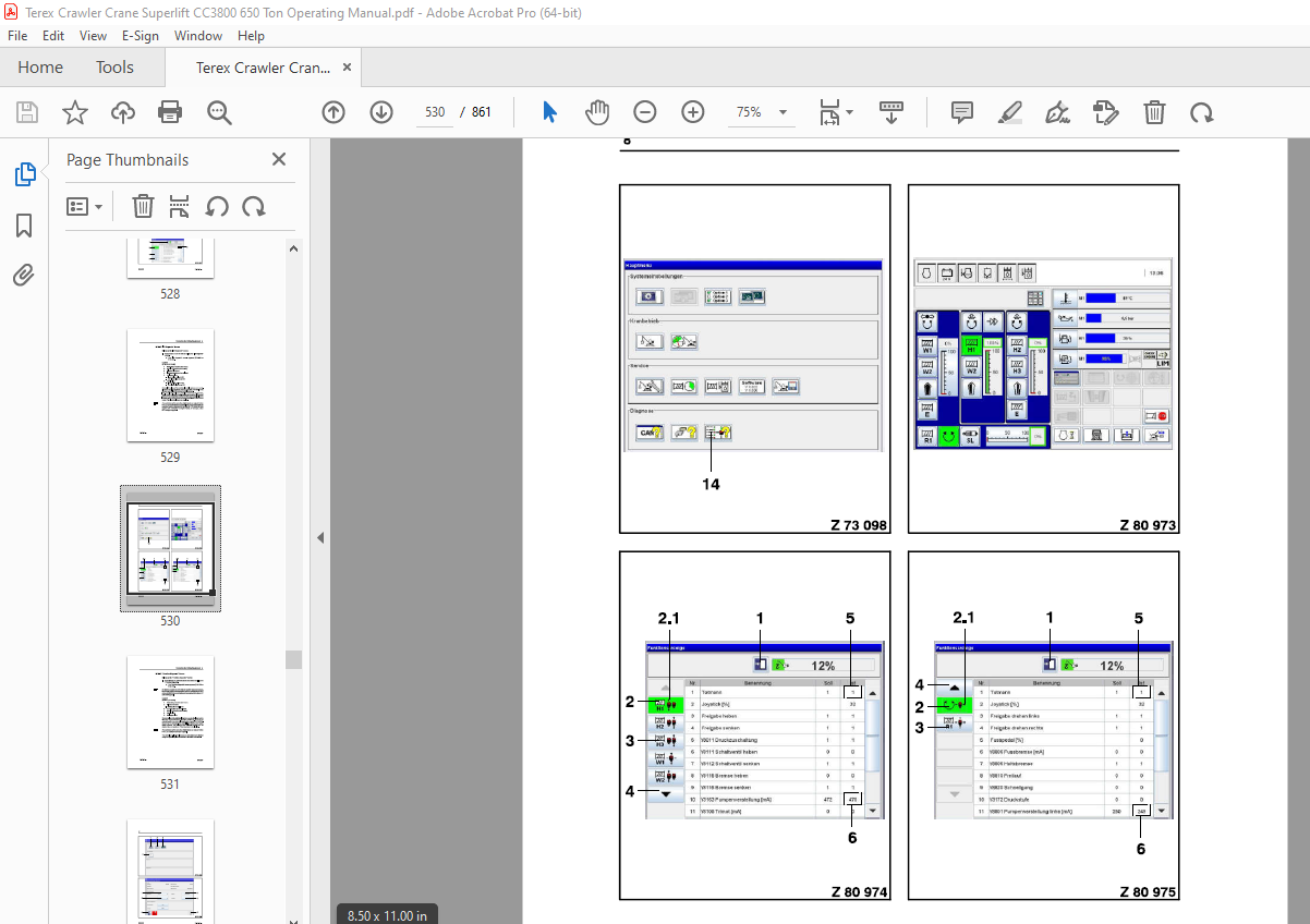
TABLE OF CONTENTS:
Terex Crawler Crane Superlift CC3800 650 Ton Operating Manual – PDF DOWNLOAD
Foreword 1
Safety lnstructions
General
lntended Use
Operating Conditions and Computed Design of the Crane
General
Classification of the Crane
Classification of the Engines
Workplace Ergonomics
Load and Utilisation of the Crane
Required Amblent Conditions
Service Life
Scrapping / Disposal
Standards and Calculation Regulations
Dangers to Air Traffic
Safety Regulations
Organisational Measures
Personnel Selection and Qualifications
Particular Hazards
Electric Energy
Gas, Dust, Steam, Smoke
Crushing / Collision
Becoming Entangled / Dragged in
Crushing/Shearing
Dangers Due to Slipping, Tripping, Falling
Comblnation of Hazards with Comblned Operation of Two or
Маге Cranes
Operating Areas of Several Cranes Overlap
Several Cranes Raising а Load Together
Crane Operation
Before Crane Operation
During Operation of the Crane
Following Crane Operation
Power Supply Failure
When AssemЫing and Dismantling Crane Components
Hand Signals
General Hand Signals
Hand Signals for Working Movements
Hand Signals for Driving Movements
Structure of the Crawler-mounted Crane
Overview
Superstructure
Crawler Chassis
Counterweight Dolly 325 t (716 5 kip)
Boom Variants
Allocation and Description of the Hook Operations with the
Relevant Boom Variants
Technical Description
Chassis
Superstructure
Additional Equipment (Options)
Hook Ыocks
Technical Data
Safety-relevant Components
General
Ladders and Catwalks
Fall Protection
Headlights
Emergency Exit
Signs
General Signs
Description and Fitting Location of the Signs
Meaning of the Signs
СЕ Safety Signs
Description and Fitting Location of the Signs
Meaning of the Signs
Safety Signs (Only for the USA)
Description and Fitting Location of the Signs
Meaning of the Signs
Crane Operator’s СаЬ
Operating Elements and Displays in the Crane Operator’s
СаЬ
Control Levers
Front Console
Overview of the Front Console
Display and Operating Elements оп the Front Console
Display and Operating Console for Monitoring the Engine and
Crane Operation
Area А – lndicator Light Area
Area В – Functional Displays
Area С – Crane Operation
Area D – Assignment with Different Screens PossiЫe
(Неге: Quick Menu)
Area Е – Engine Scaling Display
Display and Control Console LM I System
lndex
Overhead Console
lgnition Switch
Right Arm Console
Entering / Exiting the СаЬ
Tilting the СаЬ
Tilting the Crane Operator’s СаЬ
Workplace Ergonomics
Adjusting the Crane Operator’s Seat
Sunshade
Lighting Equipment
Opening / Closing Windows
Side Window, Rear Window
Front Window
Warning Lamp
Radio Remote Control
Moblle Control Panel for Emergency Control
Engine and Drive
Engine Control
Before Starting the Engine
Starting Procedure
Safety Regulations during the Starting Procedure
Starting the Engine
Jump Starting
External Start with Jump Leads
External Start with the lntegrated Socket
То Ве Observed after Starting the Engine
Standard Hydraulic System
Warming up the Hydraulic System
Warming-up Procedure
Hydraulic System for Low Temperatures
Warming up the Hydraulic System
Warming-up Procedure
Checks with the Diesel Engine Running
Faults in the SCR System (only for Engines in Accordance with
Exhaust Emission Standard ЕМ3Ь / ЕРА Тler 4i)
Operating Restrictions for Exhaust Emission Standard
ЕРА Tier4i
lnstructions for Operation
Switching Off the Engine
Automotive Driving
Load Limit Control
Driving the Crawler-mounted Crane
General
Main Driving Direction
Requirements for Road Surface Conditions
Regulations for Driving Operation
Control of the Crawler Chassis
Control Movements
Control Movements for Tailing Operation
Options for Controlling the Driving Speed
Normal Range
High Speed
Brakes
Driving without Load оп the Horizontal and Angled Road
Surface
General
Driving without Load
Driving with Load оп а Horizontal and lnclined Road
Surface
General
Driving with Load оп Horizontal, Level Terrain
(< 0 3° Gradient)
Driving with Load оп lnclined, Level Terrain
( > 0 3° Gradient)
Slewing and Braking the Superstructure
Speed Control
Slewing
Normal Operation
High Speed Operation
Switching оп the Slewing Movement with “Slewing Aid”
Braking the Superstructure
Mechanical Locking of the Holding Brake in Ореп Position
Operating the Safety Equipment
IC-1 Crane Control
Overload Cut-off Using the Load Limit Device (LLD)
Function
Bridging the Load Limit Device
Control Elements: “EN 13000” Design Compared to the
“Non-EN 13000” Design
8 1 1 2 2 Bridging the Load Limit Device in the Non-EN 13000
Version
8 1 1 2 2 1 Bridging the Shut-down of the Load-moment-reducing
Movements 13
8 1 1 2 2 2 Bridging the Shut-down of Load-moment-increasing
Movements 15
8 1 1 2 2 3 Bridging the Shut-down of AII Movements 17
8 1 1 2 2 4 Configuration Operation 19
8 1 1 2 2 5 Crane Operation 21
8 1 1 2 2 6 Operation with Bridged Crane Control 23
4
036-1000-108 _ еп
lndex
8 1 1 2 3 Bridging the Load Limit Device in the EN 13000 Version 25
8 1 1 2 3 1 Bridging the Shut-down of the Load-moment-reducing
Movements with the Setup Function 25
8 1 1 2 3 2 Bridging the Shut-down of Load-moment-increasing
Movements with the Setup Function 27
8 1 1 2 3 3 Bridging the Shut-down of all Movements with the Setup
Function 29
8 1 1 2 3 4 Bridging the Shut-down of the Load-moment-reducing
Movements with the Key-operated Pushbutton 31
8 1 1 2 3 5 Bridging the Shut-down of the Load-moment-increasing
Movements with the Key-operated Pushbutton 33
8 1 1 2 3 6 Bridging the Shut-down of all Movements with the
Key-operated Pushbutton 35
8 1 1 2 3 7 Configuration Operation 37
8 1 1 2 3 8 Crane Operation 39
8 1 1 2 3 9 Operation with Activated Setup Buttons 41
8 1 1 2 3 1 О Operation with Bridged Crane Control 43
8 1 2 Error Code ТаЫеs 45
8 1 2 1 Load Limit Device Errors 45
8 1 2 2 System Errors in the Control System 53
8 1 2 3 Error Messages from Monitoring the Operative States 63
8 1 2 4 Signal Errors оп the Sensor System and Actor Technology 69
8 1 2 5 lnformation Messages with No Effect оп Crane Control 83
8 1 3 System Start / Switching the System off 89
8 1 4 Operating the LLD System 91
8 1 5 Description of the Monitor Screens and Function Keys 93
8 1 5 1 Opening Screen 93
8 1 5 2 Main Menu of the Display and Operating Console of the LLD System
(LLD Screen) 93
8 1 5 3 “System Settings” Screen 97
8 1 5 4 “Set up Crane Туре” Screen 99
8 1 5 5 “Options Menu” Screen 101
8 1 5 5 1 Calling up the “Options Menu” Screen 101
8 1 5 5 1 1 “Options” Selection 101
8 1 5 5 1 2 “Factory Options” Selection 103
8 1 5 6 “Set up Display” Screen 105
8 1 5 7 “LLD” Screen 107
8 1 5 7 1 Section А- Configuration Display 109
8 1 5 7 2 Section В – Message Strip 111
8 1 5 7 2 1 Error display “LLD” 113
8 1 5 7 2 2 Error Display “PLC” 115
8 1 5 7 3 Section С – Crane Display 117
8 1 5 7 3 1 Display of Derricking Gear Force 119
8 1 5 7 4 Section D – Load Utilisation Display 121
8 1 5 7 4 1 Load Monitoring Equipment 121
8 1 5 7 5 Section К – Assignment with Different Screens PossiЬle (here:
“Operating Mode Selection” Screen
“Slewing and Gradient Level lndicator” Display
“Operating Range Limit” Screen
“Hook Height” Display
“Ground Pressure” Display
“Lateral Auxiliary Support” Display
8 1 5 8 “Operating Range Limit” Screen 155
8 1 5 8 1 Setting up the Various Limits 159
8 1 5 9 “Service Functions” Screen 167
8 1 5 1 О “Operating Hour Meter” Screen 169
8 1 5 10 1 Calling up the “Operating Hour Meter” Screen 169
8 1 5 10 2 Explanation of Symbols in the “Operating Hour Meter”
Screen 171
8 1 5 10 3 lmportant Code of Practise 171
8 1 5 10 4 Evaluation of the Recorded Operating Hours 175
8 1 5 11 “Winch Oil Level” Screen 177
8 1 5 12 “Software Update” Screen 179
8 1 5 12 1 Updates – General 181
8 1 5 12 2 System Software Update 183
8 1 5 12 3 Control Application Update 187
8 1 5 12 4 Crane Data Update (Crane Data) 189
8 1 5 12 5 LLD Application Update (LMI) 191
8 1 5 12 6 LLD Data Update (LMI Data) 193
8 1 5 12 7 Monitoring and Messages 193
8 1 5 13 “Data Logger” Screen 197
8 1 5 13 1 “Data Logger” Screen (Data Recorder) 197
8 1 5 13 2 “Hoist Logger” Screen 199
8 1 5 13 3 ‘Wind Logger” Screen 201
8 1 5 14 “CAN Display” Screen 203
8 1 5 15 “1/0 Diagnosis” Screen 205
8 1 5 16 “Function Diagnosis” Screen 207
8 1 5 17 Main Menu of the Display and Operating Console of the Engine
and Crane Operating System (МОТ Screen) 209
8 1 5 17 1 “System Settings” Screen 209
8 1 5 17 2 “Set up Crane Туре” Screen 211
8 1 5 17 3 “Set up Display” Screen 213
8 1 5 17 4 “МОТ” Screen 213
8 1 5 17 4 1 “Rope Limit Switch Bridging” Display 215
8 1 5 17 4 2 “Operating Hour Meter” Screen 217
8 1 5 17 4 3 “Counterweight Dolly” Display 217
8 1 5 17 4 4 “Support Frame Lift Cylinder” Display 217
8 1 5 17 4 5 “Adjustment Winch” Display 217
8 1 6 Procedure in the Event of Errors 219
8 1 6 1 Error-Free Operation/Malfunction 219
8 1 6 2 Failure of Crane Control (CAN Stop) 219
8 1 6 3 Failure of а Monitor 219
8 2 Limit Switches 221
Hoist Limit Switches 221
Bridging the Hoist Limit Switches 223
Rope End Limit Switches 225
Function 225
Release Switch System for Crane Movements 227
General 227
Assignment of the Release Buttons 227
Activating the Release Buttons 227
Working with the Superlift
Modus Operandi
Safety lnstructions for Working with the Superlift
General Safety lnstructions
Safety lnstructions for Working with SL Equipment with SL
Support Frame
Safety lnstructions for Working with SL Equipment with
Counterweight Dolly
Requirements for the Ground Conditions at the Operating
Site
Description and Design of the Superlift
Description and Design of the Standard Superlift
Description and Design of the VariaЫe Superlift (Vario Superlift)
Description and Design of the SL Equipment with Counterweight
Dolly
Working with the Crane without Superlift Counterweight
(SL Counterweight)
Working with the Crane with Superlift Counterweight
(SL Counterweight)
Preparations for Raising the Load
Preparations for Raising the Load with the Standard Superlift
Preparations for Raising the Load with VariaЫe Superlift
(Vario Superlift)
Preparations for Raising the Load with SL Equipment and
Counterweight Dolly
Raising the Load
Changing the Load Radius (Change to the Working
Radius)
Adjusting the Superlift Counterweight Radius (SCR)
Setting the Superlift Counterweight Radius (SCR) Using the
Radio Remote Control for the Superlift with Counterweight
Dolly
Setting the Superlift Counterweight Radius (SCR) Using the
Control Levers in the Crane Operator’s СаЬ for the Superlift
with Counterweight Dolly
Changing the Superlift Mast Radius
Selecting the Adjustment Winch (Vario Winch)
Automatic Adjustment of the SLC
Manual Adjustment of the SLC
Support Frame Lift Cylinder (Optional)
Selecting the Support Frame Lift Cylinders
Operating the Support Frame Lift Cylinders
Setting the Load Down
Heating and Ventilation
General
Engine-dependent Heating
Engine-independent СаЬ Heater Arrangement
Operating / Safety lnstructions
Operating Control of the Heater Timer
Air Conditioning
Liquid Gas Heating System (Optional)
lmportant Notes
Heating
Ventilation
Shutting off
Notes оп Heating Operation
Shut-Down With the Window Switch
Parking the Crane
Wind Speeds
Lowering the Boom System
Emergency Operation
Safety lnstructions
Emergency Control System with the Moblle Control Panel
Emergency Operation with the Emergency Unit
General
Emergency Unit
Description of the Emergency Unit
Hydraulic Electronic Components
Drive
Operating and Monitoring Controls
Fuel Tank
Connecting the Emergency Unit to the Crane
Starting the Emergency Unit
Driving the Crane Movements during Emergency Operation
Removing the Emergency Unit
Radio Remote Control
General
Preparing the Radio Remote Control
Connection Fault
Activating the Radio Remote Control
Radio Remote Control for AssemЫy of the Basic Unit
Radio Remote Control for Configuring
Radio Remote Control for the Adjustment Winch and Vario-
Cylinder in the Superlift Rods
Radio Remote Control for the Counterweight Dolly
Radio Remote Control for Rope Change
Driving with the Counterweight Dolly
Safety lnstructions
General
Requirements for the Ground Conditions at the Operating Site
Description of Mechanics
Basic Position and Angle Functions
Reversing (Definition)
Description of the Software
Setting the Operating Modes
Selecting the Display “Counterweight Dolly”
Selecting the Operating Mode “Tailing”
Selecting the Operating Mode “Parallel Driving”
Selecting the Operating Mode “Circular Travel”
Selecting the Radio Remote Control
Swivelling bolster Positions
Procedure when Changing Operating Mode
Shutdown Criteria
Parking the Counterweight Dolly
More products