$29
Terex Demag AC40 AC50 3-Axle Mobile Crane Operation Manual
Terex Demag AC40 / AC50 3-Axle Mobile Crane Operation Manual – PDF DOWNLOAD
FILE DETAILS:
Terex Demag AC40 / AC50 3-Axle Mobile Crane Operation Manual – PDF DOWNLOAD
Language : English
Pages : 85
Downloadable : Yes
File Type : PDF
IMAGES PREVIEW OF THE MANUAL:
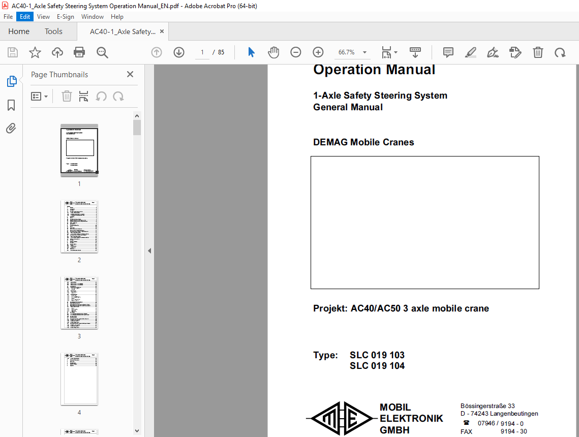
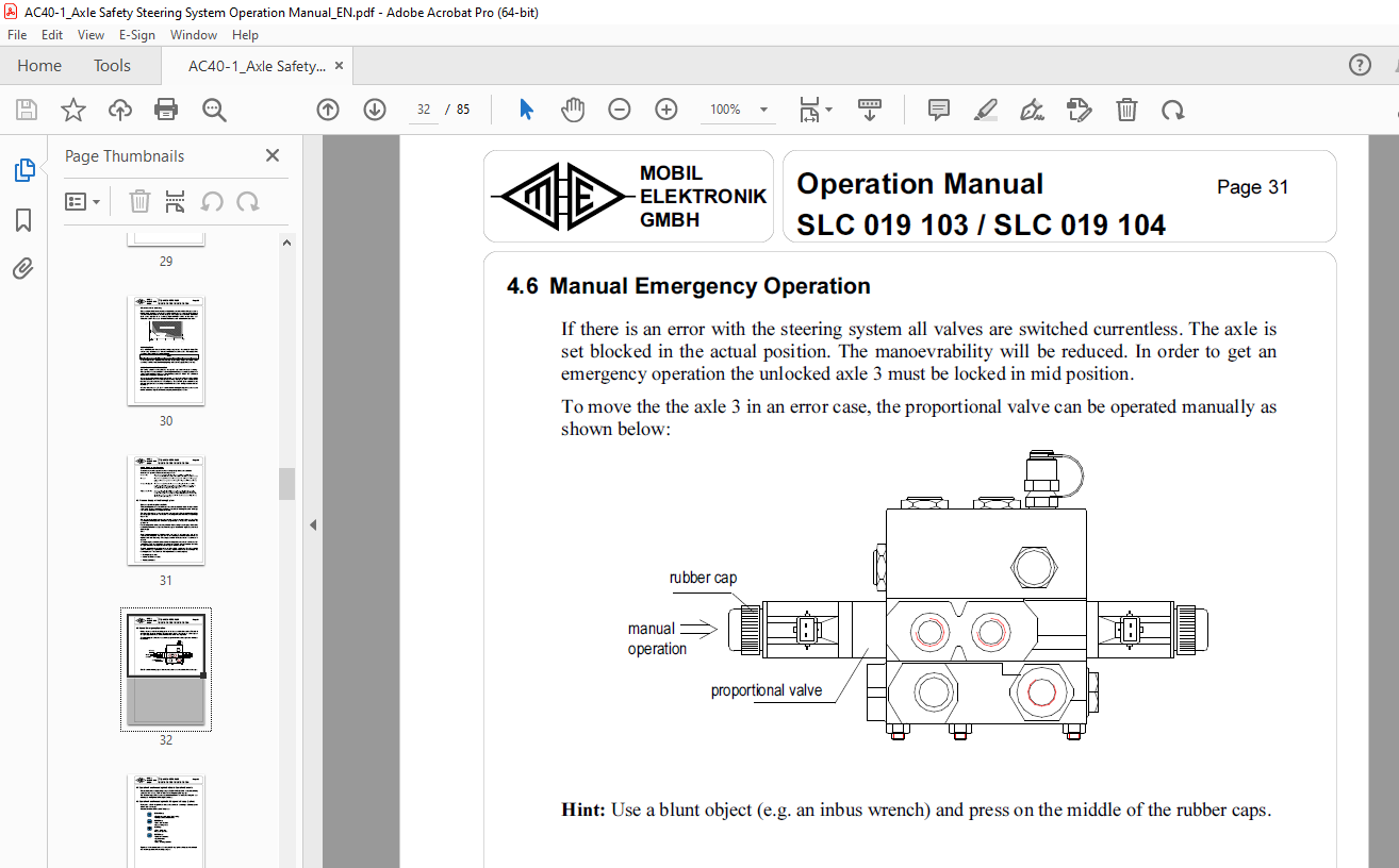
TABLE OF CONTENTS:
Terex Demag AC40 / AC50 3-Axle Mobile Crane Operation Manual – PDF DOWNLOAD
General
Documentation
Safety Hints
Safety Hints when Maintenance is Done Welding Work at the Vehicle
Steering Systems with Hydraulic Accumulator
Working in the Steering Range of the Wheels
Installation
General
Assembly of the Steering Cylinder
Mounting and Connection of the Hydraulic Units Mounting and Wiring of the Safety Angle Transducers
Wiring of the System
Common Hints
Initiation and Start-Up
General
Requirements
Control of the Electrical Installation
Connection of the Safety Angle Transducers
Axle Alignment using the On-Board Operation Elements Select an Axle for the Alignment
Safety Hints
System Description
Vehicle
Steering Computer
Safety Concept
Maintenance
Daily Check (Departure Control)
Alignment of the Mid-position and of the Mechanical Stops Axle Alignment using the CAN Diagnosis Terminal
Select an Axle for the Alignment
Alignment of the Mid-position and of the Mechanical Stops
Activating the Steering Mode
Test Drive
Operation Manual
Half-yearly Check
Check every 2 years or every 200 000 km
Check every 4 years or every 400 000 km Steering Function
Operation of the Steering System
Changing the steering behaviour
Signal lamps
Special Functions
Axle Synchronization
Error Reactions
Monitoring Functions
Speed Measurement
Monitoring of the Locking Position
Monitoring of the Steering Deviation
Lamp Test
Surveillance of the Parameter Set
Other Monitoring Functions
Pressure Supply of the Steering System
Error Memory
Manual Emergency Operation
Operation Functions using the On-Board Operation Elements
Operation Functions using the CAN Diagnosis Display (Option) Menu for Special Functions
Password
Parameter Programming
Alignment Mode
Input Output Display
Error Memory Operation using the On-board Elements
Error Memory Operation using the CAN Diagnosis Terminal: Error Lamp / Buzzer
Display of the version
Display of Operational Data using the On-Board Elements Display in error-free operation
Display of the Actual Errors
Display of faulty parameters
Display of Operational Data using the CAN Diagnosis Terminal
Display in error-free operation
Display of the Actual Errors
Display of faulty parameters
Display of Operational Data
Summary of Parameters
Error List
Wiring diagram
Hydraulic diagram
Appendix
More products